← v9 v11 →
v10: Drum-frame film stencil v1/v2 + laser alignment tests (v0 centre crosshair, v1 pattern)
Frozen Tue Oct 20, 2026, 1:41 PM ET · 398 files · folder: versions/v10_2026-10-20/ · archive: OSSO_v10_2026-10-20.tar.gz
What changed
New in this snapshot: 7 drawings, 13 STEP files, 6 documents/media.
Key decisions
Drawings new in v10
Other images
STEP files (49)
Documents & media
Journal entries in this version
2026-10-20 12:29 PM ET — Short-term process: drum-frame Kapton stencil (the designer)
Near-term with current equipment: manual stencil paste + manual placement with a handheld vacuum. Stencil: non-adhesive polyimide (~0.075–0.125 mm) tensioned in a 3D-printed drum/hoop frame (inner and outer rings, proud inner lip, rounded wrap edge), registered on the board jig tooling pins; laser-cut (355 nm UV, 10 W) in the jig in board coordinates with a Z offset, then reused as a stencil on the same pins. Test: power/speed sweep on polyimide. The long-term cell plan (jet dispense, no stencils) is unchanged.
2026-10-20 12:31 PM ET — Decision: film stencil in drum frame locked (the designer)
Locked: 0.075 mm film (the designer already has it) tensioned in a 3D-printed drum frame, laser-cut in the board jig, used as the near-term paste stencil. To confirm: whether the film is polyimide (Kapton) or polyamide (nylon). Next design: stencil laser jig + drum frame.
Confirmed (12:32 PM ET): film is polyimide (PI), non-adhesive, 0.075 × 500 × 2000 mm roll. Order screenshot saved as refs/stencil/PI_film_0075_order.png.
2026-10-20 12:36 PM ET — Drum-frame stencil design input (the designer)
Film mounting mirrors the designer's resin vat re-filming: lay film over the frame underside with a removable center support to prevent sag; place the clamp ring (recessed screw points) on top; punch the 4 corners and loosely fit the corner screws; then progressively punch, screw and tighten around the perimeter. The ring holes act as the punch guide (no pre-punched sheets). Frame features implied: a removable center support/platen, recessed counterbored screw points in the ring, inserts in the lower frame, a tensioning lip, and pin registration to the jig.
2026-10-20 12:39 PM ET — Decision: stencil frame punching (the designer)
Locked: screw holes are punched as you go by hand (vat method), outside the laser field. Only the stencil apertures are lasered, on the 150 mm galvo lens; the frame registers to the jig so the 140 mm board area sits in the 150 mm field.
Final mounting step (12:40 PM ET): trim excess film outside the clamp ring to keep it out of the way. Frame feature: an outer edge to trim against.
2026-10-20 12:47 PM ET — Drum-frame film stencil v1 modelled (approved 12:41 PM)
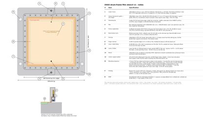
cad/stencil_v1/: lower frame 188×188×16 (224 with registration ears), clamp ring 188×188×5, center support platen 155.2×155.2×16, print jig 228×228×12; STEPs (+ assembly with board, film, pins), STL/3MF per part, build script stencil_v1.py, make_3mf.py, verify.py (all STEPs re-import valid, 0 probe fails), BOM.md, PRINT_NOTES.md. 40× M3×8 ISO 4762 into Ruthex RX-M3x5.7 (Ø4.2 × 7.0 holes), pitch 17.7 on a 177 square, outside the 150 field; window 156; rounded 4 mm lip is the lowest surface (ring 1.0 above). Registration: frame on 2× Ø6 dowels at (70,−34) round / (70,174) slot on the board datum axis; board on Ø3 (70,4) + Ø2 (70,136) as v4e. Laser the film on the print jig with the pocket empty: film top = 12.075 above table (−19.525 vs v4e board top). Drawing drawings/stencil_frame_v1.png/.pdf. Est. print 11h25 / 685 g total.
2026-10-20 1:13 PM ET — Drum-frame film stencil v2 modelled (changes approved by the designer Oct 20)
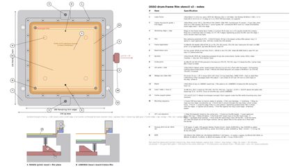
cad/stencil_v2/ (v1 untouched): lower frame 196×196×17.5 (232 with ears), clamp ring 196×196×6, center platen 155.2×155.2×17.5, jig base 234×234×38, lift carrier 158×158×14, lift slider 224×116×17. Tensioning ridge on the frame clamp face (4 wide, 2.5 proud, R1.8 crest, 172 square) + matching 3.0 step in the ring (vat-style tension). 20× M3×12 ISO 10642 countersunk (4 corners + 4 per side, pitch 36.8 on a 184 square; Ø3.4 punch guide, 90° Ø6.9 countersink sunk 0.2) into Ruthex RX-M3x5.7 (Ø4.2 × 7.5). Vertical lift: carrier on 4× Ø6×30 guide posts, wedge-cam slider (pull knob 34 = up, 8 stroke, 18° ramps to dwell flats = hard stop), 4× M3×10 ISO 4026 set-screw feet for fine adjust; board on Ø3 (70,4) / Ø2 (70,136) pins on the carrier, pin tops 0.2 below board top; carrier rim flush = full backing. Frame stays on the same 2× Ø6×26 dowels for laser and print. Laser focus: film top 38.075 above table (+6.475 vs v4e board top), carrier lowered (board 8 below film). Jig underside pocketed. STEPs (+ assembly raised/lowered) re-imported valid, verify.py 61 checks 0 fails. Drawing drawings/stencil_frame_v2.png/.pdf. Est. print ~21h25 / ~1.32 kg (CLI). Supersedes an earlier aborted v2 attempt (no partial files were present).
2026-10-20 1:27 PM ET — Version freeze v10
Frozen to versions/v10_2026-10-20 + OSSO_v10_2026-10-20.tar.gz. Since v9: drum-frame film stencil v1 and v2 (cad/stencil_v1, cad/stencil_v2, drawings/stencil_frame_v1., drawings/stencil_frame_v2.). v2 adds a tensioning ridge, 20× M3×12 countersunk screws into Ruthex M3 inserts, a wedge-slider lift that raises the board 8 mm to the film plane, and a 196 mm frame.
Practice film ordered by the designer (Oct 20): ZXAKAOSI non-adhesive polyimide, 0.075 mm, 200×300 mm, 10-pack, to test the frame and film hold and to practice laser cuts before using the special-order roll.
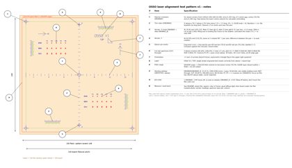
2026-10-20 1:32 PM ET — Laser alignment test pattern v1
cad/laser_align_v1/ (laser_align_v1.py → .svg/.dxf/_geom.json, README.md); drawing drawings/laser_align_v1.png/.pdf. For practice PI 0.075 film in stencil frame v2 on the jig, 150 lens; board coordinates, field centred on (70,70), extent −4…144. Layers ENGRAVE (job 1: 5 crosshair fiducials at the board corners + centre, X/Y tick rulers 10/5 mm with no baseline, vernier main scales, Ø3/Ø2 pin marks, +X/+Y arrows, triangle flag, "OSSO V1 / TOP"), ENGRAVE_B (job 2 after re-seating the frame: vernier slides 0.9 pitch, 0.1 mm/line → re-seat repeatability), CUT (job 3: 2 blocks × 3 rows (0402 0.5×0.6, 0603 0.8×0.9, SOIC 0.6×1.55) × 5 pass-count columns, 30 holes, 19.5 mm², ≥4.4 edge gap), GUIDE (off). Untested starting settings: engrave 15–25 %/1500–2500 mm/s/1 pass; cut 40–60 %/300–600 mm/s, 1–5 passes. README covers cutting, photographing and what to send back.
2026-10-20 1:39 PM ET — Laser alignment v0: centre-crosshair offset test
cad/laser_align_v0_center/ (laser_align_v0_center.py → .svg/.dxf/_geom.json/_preview.png, README.md). This step comes before v1: it finds only the laser-to-jig offset, so that a field/table-pitch offset does not put power on the PETG frame. ENGRAVE only (no cuts, lowest visible power, focus 38.075): one crosshair at (70,70) (10 mm arms, 0.5 gap, Ø4 ring) plus 5 mm +X/+Y arrows. All within r = 12.2 mm, so a 60 mm offset still stays on the film inside the 156 window. Same page/field convention as v1 (150 page, centre = lens centre). Process: frame/red-dot preview first; afterwards measure the cross centre against the board centre (board raised under the film, or calipers from the Ø3 (70,4) / Ø2 (70,136) pins), or take a square photo with a ruler. the designer sends the photo or dX/dY back, and the correction is computed.
2026-10-20 1:41 PM ET — Version freeze v10 (re-snap)
Re-frozen to versions/v10_2026-10-20 + OSSO_v10_2026-10-20.tar.gz (replaces the 1:27 PM v10 snapshot). Adds the laser alignment test pattern v1 (cad/laser_align_v1, drawings/laser_align_v1.*) and the centre-crosshair offset test v0 (cad/laser_align_v0_center), on top of drum-frame film stencil v1/v2.