New in this snapshot: 6 drawings, 1 STEP files, 2 documents/media.
2026-10-21 12:04 PM ET — PCB: BR-G1 laser-cut STEP + DXF for quoting
Laser-cut version of the BR-G1 FR4 gear disc in pcb/br_g1_v1/laser/: br_g1_laser.step, br_g1_laser.dxf, QUOTE_NOTES.md and the make_br_g1_laser.py generator. It uses the same parameters as the router fab files, but with a sharp ideal profile (no R0.5 root fillets or D-bore corner radii), 0.30 thick. Validation: one valid solid, also valid after re-import, volume 108.757 mm³, tip R12.000 / root R9.750 (bbox 23.99 x 23.85 x 0.30 because the tooth tips are chords off the axes), D-bore 3.00 / 2.50, and 16 round holes in the right positions (12x 0.30 R8, 1.0 R6 at 0°, 3x 0.80 R3). The DXF is in mm with 2025 lines, 1 arc and 16 circles. Quote notes ask for 10 and 25 pieces, FR4 first (polyimide or stainless later), and ±0.02 on the 0.30 holes.
2026-10-21 12:15 PM EDT — BR-G1 decision: FR4 PCB over laser-cut 304 stainless
the designer compared the BR-G1 gear disc as a PCBWay laser-cut 304 stainless part with the fab-made 0.30mm FR4 PCB. The costs are very similar, but PCBWay lists laser cutting at ±0.1mm, which is too loose for the 0.30mm pockets, while a PCB's drilled unplated holes hold ±0.05mm with tighter hole positions. Decision: make BR-G1 as an FR4 PCB using pcb/br_g1_v1. The laser STEP and DXF in pcb/br_g1_v1/laser/ are kept as an alternate, for a precision etching or fiber-laser shop later.
2026-10-21 12:25 PM EDT — BR-G1 ordered from PCBWay
2026-10-21 12:29 PM ET — DECISION (the designer): flux dispensing for tinning = syringe head on its own Neptune 4
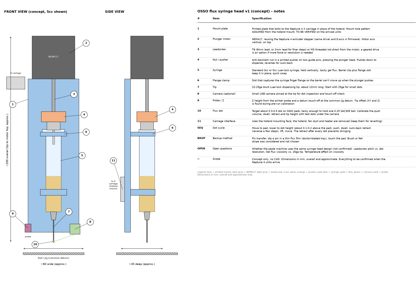
Flux for the tinning step is dispensed by a syringe applicator on its own Neptune 4 (bed-slinger). It uses the same common jig datum and pre-run calibration as the other machines. The flux is tacky gel flux pushed by a stepper-driven plunger (leadscrew or the E-stepper) through a 22-25ga blunt tip, with a suck-back retract after each dot to prevent stringing. Flux dots must be tacky enough to hold a 0.25mm ball in place. Backup: pin transfer (dip a pin in a thin flux film, then touch the pad). A brush or felt stripe was considered but not chosen. Not confirmed yet: whether the paste machine shares the same syringe head design. Concept drawing: drawings/osso_flux_syringe_head_v1.
2026-10-21 12:48 PM ET — CONCEPT (the designer approved): OSSO Test Board (tester)
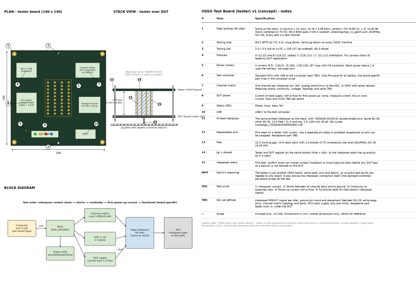
The tester is itself an OSSO board. It lands on the board under test (DUT) through the same printed pogo interposer and the same jig datum as a real stack, so the interposer pads double as test pads and no board needs extra test points. the designer's reasoning: the tester uses the same pads, pins and datum, and it also verifies the interposer connection itself. One standard test controller covers every board, and a per-board script on the computer does the rest.
- Tester hardware: a standard MCU with USB to the computer; one channel per interposer pin (analog switch/mux plus ADC, or GPIO with a series resistor) for shorts, continuity and voltage; a current-limited DUT supply with an e-fuse for first power-up; status LEDs.
- Test script order: interposer contact check, then shorts, continuity, power-up current, and finally functional tests for that board's interposer signals.
- Pogo pins wear (10k cycles), so the tester uses replaceable pins (a pin plate or socketed receptacles).
- Interposer spec used (from the files): 40 sites, 4 x 10 at 10.16 x 5.08 pitch, centered on (70,70), with Ø3.0 ENIG pads in Ø4.0 isolation (drawings/top_v1i_geom.json). Pin YZD0029-20135-01 (cad/pogo_YZD0029/DIMENSIONS.md). 12.0 gap, 13.6 pitch. Datum: Ø3.0 tooling hole at (70,4), slot at x=70 y 135-137, fiducials A/B/C/C'. Power corners at (5,5), (135,5), (5,135), (135,135).
- TBD: interposer pinout, ground pin count and placement, channel topology and parts, MCU, supply rails and limits, receptacle part, tester over vs. under the DUT.
Concept drawing: drawings/osso_test_board_v1.py/.png/.pdf.
2026-10-21 12:59 PM EDT — Test board power: DC rail through corner posts via e-fuse
the designer confirmed that the DC rail always runs through the corner posts and brass standoffs, the same as on the base board, with no separate rail. On the OSSO Test Board, the tester's corner posts are split into an input side and an output side. Supply power comes in, goes through the tester's current-limited e-fuse (switched and metered), and then goes out through the corner posts and standoffs to the board under test. This keeps the standard power path while still giving a current-limited first power-up. It resolves the open item on DUT supply rails and current limits in osso_test_board_v1 as to the path; the rail voltages and current limit values are still to be decided.
2026-10-21 1:00 PM EDT — Test board pins: standard interposer architecture
the designer decided the OSSO Test Board uses the standard interposer architecture and the same pogo pin (Xinyangze YZD0029-20135-01), not a different or replaceable pin plate. Note: on a test interposer, all or more of the 40 sites may be populated, including sites the board under test uses only as test pads. This resolves the open item on the pin receptacle or pin plate part in osso_test_board_v1. Pin wear (rated 10k cycles) is handled by replacing pins or the printed interposer as needed.
2026-10-21 1:00 PM EDT — Test board orientation: tester under the board, quick clamp
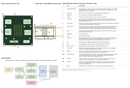
the designer decided the OSSO Test Board sits under the board under test, the way a base board would, and a quick clamp holds the stack (tester, interposer, board under test) together for compression. This resolves the open item on whether the tester sits over or under the board in osso_test_board_v1. The clamp design is not done yet; it should register on the same datum (tooling hole and slot) and compress the pogo pins to the 12.0 working gap.
2026-10-21 1:05 PM ET — DECISION (the designer): universal OSSO Test Board, hybrid matrix
Pin assignments belong to each board under test and change from board to board. To keep the number of tester designs and copies small, the tester is universal: all 40 interposer sites get identical flexible channels, and the per-board test script assigns each site's role.
- Chosen architecture (hybrid): an analog switch matrix connects any site to shared buses (GND, current source and sense, ADC, drive/GPIO) for shorts, continuity and voltage. A subset of sites can also be switched to fast MCU pins for functional signals (I2C/SPI/UART), chosen by the script.
- Board ID: each board under test carries an ID (EEPROM or an ID resistor on a known site). It is read first, and the matching pin map and tests are loaded.
- Earlier decisions today, already journaled: the DC rail runs through the corner posts via the tester e-fuse (12:59 PM); the standard interposer and pins, with all or more sites populated (1:00 PM); the tester sits under the board under test with a quick clamp (1:00 PM).
2026-10-21 1:08 PM ET — VERSION v13 snapped
Milestone: the tester strategy is set, a universal OSSO Test Board. Frozen to versions/v13_2026-10-21 + OSSO_v13_2026-10-21.tar.gz (the project without versions/, video/, stray root tarballs and ._* files). Since v12: BR-G1 laser-cut STEP/DXF and quote notes; BR-G1 ordered from PCBWay (50 discs); the decision to spray a conformal finish after assembly; flux dispensing by a syringe head on its own Neptune 4, with concept drawing osso_flux_syringe_head_v1; the OSSO Test Board concept (osso_test_board_v1) and its decisions (DC rail through corner posts via e-fuse, standard interposer and pins, tester under the board under test with a quick clamp); the universal hybrid matrix with board ID first (osso_test_board_v2, refs/test_board_matrix_sizing.md); and TODO.md updates (flux head and test board tracks). The docs site now lists v13.