← v14 v16 →
v15: Two-piston FOC pump calc, all-metal Luer, 300 mm bed slinger, TH jig + bottom reflow first, bonded needle tips, PnP part storage (pods/strips/matrix) drawing
Frozen Sat Oct 24, 2026, 7:06 PM ET · 1035 files · folder: versions/v15_2026-10-24/ · archive: OSSO_v15_2026-10-24.tar.gz
What changed
- 2026-10-23 10:58 AM EDT - Design thoughts from the designer (notes only)
- 2026-10-23 11:00 AM EDT - Design thought: needle gauge check at startup (notes only)
- 2026-10-23 1:39 PM EDT - Alternative suppliers for the electropermanent latch magnet (research only)
- 2026-10-23 1:48 PM EDT - Design note: 3D manifold on the head (notes only)
- 2026-10-23 1:48 PM EDT - Design note: resin printing for better seals (notes only)
- 2026-10-23 1:54 PM EDT - Design discussion: air compression (notes only)
- 2026-10-23 1:56 PM EDT - Air compression: turbine dropped, FOC ideas (notes only)
- 2026-10-23 1:58 PM EDT - Air compression direction: calibrated piston profiles (notes only)
- 2026-10-23 2:21 PM EDT - Pump piston sizing vs tank-like supply (calculation only)
- 2026-10-23 2:31 PM EDT, Two-piston alternating pump (discussion and calculation start)
- 2026-10-23 2:53 PM EDT, Two-piston alternating pump: calculation result (calculated, not measured)
- 2026-10-23 2:59 PM EDT, Two-piston compression: the designer's reasons and status
- 2026-10-23 4:03 PM EDT, Observation: the pump design resembles a syringe pump
- 2026-10-23 8:29 PM EDT, Decision: all-metal Luer needles for consistency
- 2026-10-23 8:33 PM EDT, Decision: larger bed slinger base
- 2026-10-23 8:34 PM EDT, Design note: solder ball drop above the needle array
- 2026-10-23 8:35 PM EDT, Milestone judgment: system feasible
- 2026-10-24 9:41 AM EDT — Design note: TH parts by jig + underside solder rings
- 2026-10-24 9:42 AM EDT — Process flow decision: bottom reflow first
- 2026-10-24 9:44 AM EDT — Correction: TH bodies sit on top; top reflow must navigate them
- 2026-10-24 9:45 AM EDT — Design rule: lay out boards with reflow in mind
- 2026-10-24 9:50 AM EDT — Design note: 3D-printed needle tips
- 2026-10-24 9:52 AM EDT — Decision: bond 3D-printed needle tips
- 2026-10-24 9:55 AM EDT — Design note: calibration feature for zeroing tips
- 2026-10-24 4:37 PM EDT — Component storage and PnP delivery: cells and trays
- 2026-10-24 4:38 PM EDT — Correction: 0402 is the smallest part; two cell (carrier) sizes
- 2026-10-24 4:39 PM EDT — Decision: cell grid of 10 mm and 20 mm
- 2026-10-24 5:22 PM EDT — Decision: oversize parts and a manual park spot
- 2026-10-24 5:59 PM EDT — Decision: try the magazine first, as a wall of drawers
- 2026-10-24 6:01 PM EDT — Decision: drawer wall behind the bed
- 2026-10-24 6:02 PM EDT — Design note: rail detail built into the carrier box
- 2026-10-24 6:06 PM EDT — Decision: gravity detent for the drawers
- 2026-10-24 6:06 PM EDT — Topic: loading the drawers
- 2026-10-24 6:09 PM EDT — Decision: one-row cell carrier as a nested container
- 2026-10-24 6:18 PM EDT — Decision: QR code on each one-row carrier, stored as inventory
- 2026-10-24 6:22 PM EDT — Decision: names for PnP part storage
- 2026-10-24 6:23 PM EDT — Decision: manual strip loading for offline storage
- 2026-10-24 6:25 PM EDT — Decision: intelligent camera confirmation when strips load into the matrix
- 2026-10-24 6:26 PM EDT — Decision: matrix positions chosen for PnP efficiency
- 2026-10-24 6:45 PM EDT — Design logic review: conflicts found
- 2026-10-24 6:45 PM EDT — Decision: two hooks, one on the bed and one on the head, open the matrix drawers
- 2026-10-24 6:59 PM EDT — Decision: matrix stays at the back; lift latch with no actuator, opened by bump to lift
- 2026-10-24 7:06 PM EDT — Snap v15
New in this snapshot: 2 drawings, 0 STEP files, 3 documents/media.
Key decisions
Drawings new in v15
Other images
STEP files (202)
Documents & media
Tools snapshot
Source: versions/v15_2026-10-24/refs/TOOLS.md
Tools used as of this version
OSSO tools inventory
Software, libraries, file formats, techniques and services actually used on OSSO, found from the scripts in cad/, drawings/, pcb/, fab/, laser-test/, site_build/, the installed environments (/workspace/.cadvenv, system packages) and JOURNAL.md. Versions are what is installed on the box as of 2026-10-23. Two box venvs exist: /workspace/.cadvenv (older) and /workspace/.cadenv (CadQuery 2.8.0 + pyvista + trimesh, used for the tool-drop v2d model). "Not installed now" means a past script used it but the current box env lacks it.
CAD generation (3D)
| Tool |
Version |
Used for |
First used/Files |
Python (venv /workspace/.cadvenv) |
3.13.5 |
Runs every generator and verifier script |
Oct 14; all *.py |
| CadQuery |
2.8.0 |
Parametric solids for jigs, boards, stencil frames, dispenser POCs; STEP/STL export (cq.exporters.export), STEP re-import (cq.importers.importStep) |
Oct 16, cad/jig_v4b/jig_v4b.py; all cad/*/make_*.py |
| OCP (cadquery-ocp, OpenCASCADE bindings) |
7.9.3.1.1 |
Low-level B-rep work: BRepCheck_Analyzer validity, volume props, booleans |
cad/*/verify*.py, dispenser POC v3-v5 |
| numpy |
2.5.4 |
Geometry math (involute gear profiles, hole patterns, sweeps) |
most CAD/drawing scripts |
| shapely |
2.2.0 |
2D outlines, morphological closing, unary_union for gear/disc profiles |
pcb/br_g1_v1/make_br_g1.py, laser profiles |
| scipy |
1.18.1 |
Installed CadQuery dependency; numeric helpers |
venv |
| casadi / nlopt |
3.8.1 / 2.11.0 |
CadQuery solver dependencies (assemblies/sketch constraints) |
venv |
| vtk |
9.6.2 |
CadQuery visualization backend |
venv |
pyvista (venv /workspace/.cadenv) |
0.49.1 |
Offscreen preview renders of STL/STEP models (iso, close-up, section views) |
Oct 16-19, versions/v5_2026-10-19/cad/*/render.py; Oct 23, cad/tool_drop_mech_poc_v2d/render_preview.py |
| trimesh |
5.1.1 (venv /workspace/.cadenv) |
STL watertight/extent checks |
cad/stencil_v1/verify.py |
Fit check / interference method
| Tool |
Version |
Used for |
First used/Files |
CadQuery/OCC boolean intersect + Volume() |
2.8.0 / 7.9.3 |
Pairwise intersection volume between parts re-imported from the exported STEP; 0 mm³ = no interference |
Oct 21, cad/ball_dispenser_poc_v3..v5 |
OCC BRepExtrema_DistShapeShape |
7.9.3 |
Minimum clearance between non-touching parts at each sweep state (bbox prefilter first); an explicit list of intended contacts is excluded |
Oct 23, cad/tool_drop_mech_poc_v2d/ |
| Mechanism torque/force sweep |
(technique) |
Moment arm sign and size, dead-center margin, deploy/release/hold margins at mu 0.2 / 0.3 / 1.5x seal friction, pass/fail gate in fit_check.json |
Oct 23, refs/tool_drop_*, cad/tool_drop_mech_poc_v2d/ |
| Angular sweep |
(technique) |
Rotate moving parts in 2° steps (0-20°/0-30°), re-check intersection volume and minimum gap at each step (gear mesh backlash 0.035-0.037) |
POC v4/v5 |
| Probe cylinders |
(technique) |
Thin cylinders along fill/exit axes intersected with exported disc STEPs to prove paths open or blocked; hole-axis alignment asserted to 0.000 |
POC v4/v5 |
| Tolerance-case matrix |
(technique) |
All thickness combinations (e.g. 0.25/0.30 carrier, 0.711-0.813 cover) checked for pocket gap and overlap |
POC v3-v5 |
| STEP re-import + validity |
(technique) |
Every exported STEP re-read, solids counted, isValid(); STLs watertight |
Oct 16 jig v4b onward |
Drawings and 2D
| Tool |
Version |
Used for |
First used/Files |
| matplotlib |
3.11.2 |
All engineering drawings (plan, section, exploded) to PNG and multi-page PDF (PdfPages) |
Oct 15; drawings/*.py |
| ezdxf |
1.4.5 |
DXF cut profiles (laser tests, alignment patterns, BR-G1 laser, BR-C1 covers) |
laser-test/gen.py, cad/laser_align_*, br_c1_v2.dxf |
| SVG (hand-written) |
(format) |
Laser test/alignment patterns for LightBurn |
laser-test/*.svg, cad/laser_align_*/*.svg |
| Pillow |
12.3.0 (system) / 13.0.0 (venv) |
Site thumbnails, image compositing |
site_build/build_site.py |
| fontTools, kiwisolver, contourpy, pyparsing |
4.67.0 / 1.5.1 / 1.4.0 / 3.3.3 |
matplotlib dependencies |
venv |
PCB: KiCad, Gerber, drill, DRC
| Tool |
Version |
Used for |
First used/Files |
| KiCad / kicad-cli |
9.0.2 |
.kicad_pcb written by script, then kicad-cli exports Gerbers, Excellon drill, job file, and runs DRC (drc.rpt, 0 errors) |
Oct 21, pcb/br_g1_v1/make_br_g1.py, pcb/br_g2_v1/ |
| Hand-written RS-274X X2 + Excellon |
(technique) |
First Gerber set before KiCad was on the box |
Oct 16, fab/gen_v3b_gerbers.py |
| gerbv |
2.10.0 |
Render Gerbers back to PNG for visual check |
Oct 16, fab/render/, pcb/br_g1_v1/preview_gerbv.png |
| Gerber/Excellon re-parse verifier |
(technique) |
Re-read output files, count teeth/holes, compare to geometry report |
pcb/br_g1_v1/verify_br_g1.py, verify_report.json |
3D printing and laser
| Tool |
Version |
Used for |
First used/Files |
| Bambu Studio (AppImage, headless slice) |
02.08.02.61 (box); the designer 02.08.02.60 |
3MF projects for P1S, headless slice estimates |
Oct 16, cad/jig_v4*/make_3mf.py, /workspace/tools/bambu |
| LightBurn |
the designer's copy |
UV galvo laser jobs from SVG/DXF |
Oct 16, laser-test/settings.md, refs/laser/ |
| Klipper (Elegoo Neptune 4) |
stock |
Planned PnP / flux syringe motion |
Oct 21, journal |
File formats
| Format |
Tool |
Used for |
First used/Files |
| STEP (.step) |
CadQuery/OCC |
Parts and assemblies for the designer's CAD and vendors |
Oct 16, cad/*/*.step |
| STL |
CadQuery |
Print meshes |
Oct 16, cad/jig_v4b/*.stl |
| 3MF |
make_3mf.py |
Bambu Studio projects |
Oct 16, cad/jig_v4b/*.3mf |
| DXF / SVG |
ezdxf / script |
Laser and SendCutSend cut files |
Oct 15, laser-test/, br_c1_v2.dxf |
| Gerber X2, Excellon, .gbrjob, zip |
kicad-cli / script |
PCB fab uploads |
Oct 16, fab/, pcb/*/gerbers |
| PNG / PDF |
matplotlib |
Drawings |
drawings/ |
| JSON / Markdown |
Python |
Geometry/verify reports, notes, journal |
throughout |
| MP4 |
(video generation) |
Vision reels |
Oct 15, video/ |
PDF tools
| Tool |
Version |
Used for |
First used/Files |
| matplotlib PdfPages |
3.11.2 |
Multi-page drawing PDFs, tech sheets |
drawings/*.pdf, refs/laser/laser_tech_sheet.pdf |
| poppler-utils (pdftoppm, pdftotext, pdfunite) |
25.03.0 |
Rasterize/read PDFs (datasheets, checks), merge pages |
refs/ datasheets |
Docs site
| Tool |
Version |
Used for |
First used/Files |
| build_site.py (custom static generator) |
in repo |
Builds site/ from JOURNAL.md, TODO.md, PENDING, refs, versions |
Oct 20, site_build/build_site.py |
| Python-Markdown (extra, sane_lists) |
3.11.1 (system) |
Markdown to HTML |
build_site.py |
| check_links.py |
in repo |
Verifies every relative link and anchor |
site_build/check_links.py |
Versions, sync and backup
| Tool |
Version |
Used for |
First used/Files |
| GNU tar + gzip |
1.35 |
Version snapshots versions/OSSO_vN_DATE.tar.gz; sync bundles |
Oct 15, versions/ |
| sha256sum / split (coreutils) |
9.7 |
Chunked tar transfer to the designer's Macs with checksum verification (hourly sync) |
Oct 21 restore from work Mac copy |
| Google Drive mirror |
(connector) |
Daily mirror of the project, done by another assistant |
daily |
| ffmpeg |
7.1.5 |
Video/media handling |
video/ |
Research and fab services
| Service |
Version |
Used for |
First used/Files |
| Web research (search + fetch) |
live |
Vendor specs and prices |
throughout |
| PCBWay |
web |
Blank v3b (5 pcs ENIG), 5 OSSO boards, 50 BR-G1 discs; laser-cut tolerance check |
Oct 16, fab/, pcb/br_g1_v1/README_FAB.md |
| SendCutSend (site + spec API scs-specs-platform) |
web |
304 SS .030" limits; BR-C1 v2 covers ordered; Oct 23: 1008 CRS .074" armature plate for the tool-drop EPM latch (DXF) |
Oct 21, cad/ball_dispenser_poc_v5/br_c1/QUOTE_NOTES.md |
| Chip Quik |
web |
SAC305 ball/paste pricing for per-board solder cost |
Oct 21, journal |
| LCSC |
web |
Pogo pin YZD0029 datasheet drawing |
Oct 16, cad/pogo_YZD0029/ |
| eBay (NV Liquidation) |
web |
2x Neptune 4 parts units |
Oct 21, journal |
| Literature (DOI) |
web |
EPTC 2012 tacky flux ball attach; IRJMETS flip chip flux |
Oct 21, journal |
AI assistant
| Tool |
Version |
Used for |
First used/Files |
| OSSO assistant in the Grok Bot app |
app |
All scripting, CAD, drawings, fab files, site and journal, with background helper agents for parallel tasks |
Oct 14 onward |
Journal entries in this version
2026-10-23 10:58 AM EDT - Design thoughts from the designer (notes only)
1) Needles are easily replaceable or cleanable thanks to the Luer lock. 2) Depending on the task, more than one tool could be deployed at once without a tool change (for example clean and dry); this only changes the kinematic constraints (arm-to-arm clearance, shared pressure/vacuum supply, combined latch loads). 3) Tool changes should be fast. 4) For heated PCB operations, a zoned heater like a 3D printer bed could reflow one section at a time. No drawing or model work requested.
2026-10-23 11:00 AM EDT - Design thought: needle gauge check at startup (notes only)
the designer: stainless needles often have the gauge laser marked on them, so one of the system cameras can check that the correct needle is installed as part of startup. Open points: camera resolution at close range, needle pose and lighting, mark legibility. No drawing or model work.
2026-10-23 1:39 PM EDT - Alternative suppliers for the electropermanent latch magnet (research only)
2026-10-23 1:48 PM EDT - Design note: 3D manifold on the head (notes only)
the designer: matrix all of the multiple air lines to the tools in a 3D manifold, to reduce tubing and connectors in the moving head. No drawing or model requested yet.
2026-10-23 1:48 PM EDT - Design note: resin printing for better seals (notes only)
the designer: use resin printing for the manifold and pneumatic parts for a better seal. To check: brittleness at thin walls and threads (use inserts or metal fittings), post-cure and wash, O-ring material compatibility. No drawing or model requested.
2026-10-23 1:54 PM EDT - Design discussion: air compression (notes only)
the designer wants to think through an on-demand compressor with FOC motor control for much finer control (advantages: no tank cycling, quiet, regulator-free pressure control, soft start, current diagnostics), and pushed further to tankless with a turbine pressure increase. My rough estimate (unverified): a 5:1 ratio needs about 500 m/s tip speed on one centrifugal stage (about 500,000 rpm at 20 mm), and the load is tiny and bursty (under 0.5 L/min average, about 55 mL per actuation), so a turbine would be far off its efficient range. Alternative: FOC-driven positive-displacement pump (piston, diaphragm or scroll) with the manifold volume plus a tiny accumulator as buffer. Compressor work stays in notes; no calculation or drawing requested yet.
2026-10-23 1:56 PM EDT - Air compression: turbine dropped, FOC ideas (notes only)
the designer dropped the turbine idea; the aim is to use an FOC motor for more precise low-flow, high-pressure control. Ideas offered: position-controlled piston pump (known volume per revolution), pressure from motor current (possible sensor replacement or cross-check), leak and wear diagnostics at startup, metered dosing puffs, vacuum from the same pump, stroke shaping to cut ripple, current limits for safety. No calculation or drawing requested.
2026-10-23 1:58 PM EDT - Air compression direction: calibrated piston profiles (notes only)
the designer agreed: a system that learns how to deliver a given volume and pressure at the delivery point with active control, not a generic holding pressure. Deliver flow and pressure as a calibrated piston movement profile (FOC-driven piston pump). Implied: calibration step per tool and line (volume, valve response), stored profiles. No calculation or drawing requested.
2026-10-23 2:21 PM EDT - Pump piston sizing vs tank-like supply (calculation only)
refs/pump_piston_sizing_v1.md/.png. Answer: size alone does not make a pump piston look like a tank; it has to be actively driven. Passive chamber, 1 m of 4 mm OD (ID 2.5) line, 35 ms deploy: sag 11.7 pct (O16), 8.7 pct (O25), 4.1 pct (O40, 99 mL); static buffer for 2 pct droop is 83 mL isothermal with the valve at the cylinder, about 300 mL with a vented 1 m line. Active piston replaying a calibrated volume profile: 1.1 pct sag learned, 2.6 pct simple profile plus PI, versus 4.1 pct for an ideal tank behind the same line. Demand: swept 0.816 mL cap / 0.701 mL rod; free air per cycle 9.1 mL cylinder only, 49 mL with vented 1 m lines. Tube holds 4.9 mL/m at ID 2.5. Recommendation: active drive, O16 piston (about 83 N at 60 psi), head manifold 5-10 mL, umbilical 1 m or less, valve-to-cylinder 0.3 m or less, 6 mm OD umbilical if possible, deploy 35 ms or slower, low-inertia drive, calibrate with a manifold pressure transducer. Open: deploy time (14-46 ms vs 100-300 ms assumed), recharge from vented air each cycle, 62-67 psi overpressure, simple vs learned profile, rotor inertia and drive type. All calculated, not measured; valve Cv, polytropic n, motor inertia assumed.
2026-10-23 2:31 PM EDT, Two-piston alternating pump (discussion and calculation start)
- the designer asked about two pistons and two FOC motors alternating. Pros: recharge hidden off-cycle, smaller pistons, smoother supply, redundancy, cross-check of motor currents. Cons: double parts and electronics, hand-off control, doubled calibration, back-to-back action limits, mass in the head (likely off-head with umbilical line lag).
- the designer: more parts is fine because the chamber prime can be done off cycle with the idle active piston. He commanded "Calculate" (calculation only). Dispatched to refs/two_piston_alternating_v1.
- Earlier today: terminology settled. "Active" means FOC fine control over the push. the designer passes on a tank for instant response. Tool change under 1 s is fine for now.
- Pros and cons of the active FOC piston given (notes): known volume per rev, pressure from motor current, diagnostics, current limits; cons: calibration plus transducer, recharge problem, 62-67 psi overshoot, inertia-driven torque, seal wear, drift, failure behavior.
2026-10-23 2:53 PM EDT, Two-piston alternating pump: calculation result (calculated, not measured)
- Files: refs/two_piston_alternating_v1.md/.png and _code/ (run_all.sh, about 45 s).
- Ø16x40 piston, 5 mm lead screw, 6000 rpm, 0.125 N·m continuous / 0.375 N·m peak motor. A priming stroke gives 5.99 mL free air in 0.168 s, 0.156 N·m peak, about 12 W mean. Motor is not the limit for priming.
- Prime time, one vs two pistons: 9 mL 0.34 vs 0.17 s; 13 mL 0.51 vs 0.34 s; 21 mL (0.3 m lines) 0.67 vs 0.34 s; 49 mL (1 m lines) 1.52 vs 0.84 s. Minimum back-to-back interval with two pistons: 0.27, 0.44, 0.44, 0.94 s.
- Initial prime from atmosphere: 1.33 s (Ø16), 2.52 s (Ø12), 0.83 s (Ø20). Average electrical power about 10-17 W; peak about 98 W per stroking piston. Discharge temperature 384-466 K.
- Hand-off with one check valve per piston: manifold dip 0.4-0.6% at 16-31 ms deploys, 0.16% or less at 35-300 ms. A 5-10 mL junction buffer makes it worse; a 10 mL head manifold helps. Umbilical length and servo bandwidth matter more than the hand-off.
- Cylinder sag at 16/31 ms: one Ø16 5.3/7.1%; two Ø16 sequential 4.0/2.2%; one Ø20x50 4.7/3.0%. Learned profile 0.1-1.4% but piston chamber reaches 74-87 psi.
- Holding torque: ready piston at 60 psi = 83 N on screw, 0.074 N·m (59% of continuous). Needs a brake, self-locking screw, or priming just before use.
- One piston out: rate falls to 57-72%; the 49 mL case then misses the 1 s target.
- Recommendation: valve at the head, vented line 0.3 m or less, two Ø16x40 pistons (or Ø20x50), 4 mm umbilical, 10 mL head manifold, meter the deploy to 35 ms or slower, avoid 1 m vented lines. At 100-300 ms deploys one piston is enough for 9-21 mL cases; the second adds redundancy and fast-event capacity.
- Open: cap fill after arm stops and retract not in the ODE; check-valve leakage and heat into umbilical not modelled; bench measurement needed.
2026-10-23 2:59 PM EDT, Two-piston compression: the designer's reasons and status
- the designer likes the two-piston FOC concept for four reasons: (1) redundancy, since one pump can run slower; (2) the prime step can anticipate the next operation (tool change or light puff) and prepare accordingly; (3) no accumulator to maintain, so no condensate to empty; (4) much more calibrated delivery with process control.
- Status: innovative concept only. Not part of the immediate test phase; first tests keep a simple 60 psi supply. Notes only, no drawing or model.
2026-10-23 4:03 PM EDT, Observation: the pump design resembles a syringe pump
- the designer observed that the two-piston FOC compression concept feels like a syringe pump: a motor-driven piston with known volume per revolution, position-controlled stroke and metered dosing. Differences: gas is compressible (pressure matters as much as volume) and the pump needs check valves to prime from atmosphere. Syringe pump techniques (fine position control, backlash handling, stall detection from motor current) carry over. Two alternating pistons resemble a dual-syringe continuous-flow pump. Observation only; no calculation, drawing or model.
2026-10-23 8:29 PM EDT, Decision: all-metal Luer needles for consistency
- the designer: use all-metal (stainless needle, stainless hub) Luer-lock needles for consistency across the needle stations. Five stations today: A flux, B PnP vacuum + θ, C ball drop 23 ga, D IPA clean + air dry, E hot-air reflow (six if dry splits from clean).
- E keeps the standard Luer lock: stainless Luer socket on the arm, heat break between heater and socket (protects arm, EPM latch, printed parts), swappable all-metal tips in several gauges, startup camera gauge check and Z touch-off apply.
- Watch-outs: the metal taper must seal without elastomers (or a high-temp PTFE/graphite washer) on E; cool-down before a manual swap or a safe-to-touch signal; stainless thread galling (light high-temp anti-seize).
- Notes only; no drawing or model.
2026-10-23 8:33 PM EDT, Decision: larger bed slinger base
- Five tool-drop stations at 22 mm body width give about 110 mm head width side by side (114-118 mm with 1-2 mm gaps; rough, not modelled). Reaching a 140x140 mm OSSO PCB with every needle needs about 228 mm X travel, which a standard 220-235 mm bed slinger barely covers with no margin for cameras, probing and parking.
- the designer: use a larger (300 mm class) bed slinger base. Watch Y moving mass (heated bed, carrier, zoned heater). A staggered two-row head stays an option to cut the needle spread.
- Notes only; no drawing or model.
2026-10-23 8:34 PM EDT, Design note: solder ball drop above the needle array
- the designer imagines the solder ball dispenser (hopper + disc) fitting above the needle array, complex but feasible. Keeps head width at about 110 mm. Costs: head height and a higher center of mass on the moving head. The ball path must work with station C's folding arm (feed aligned with the pivot or a short flexible guide). Notes only.
2026-10-23 8:35 PM EDT, Milestone judgment: system feasible
- the designer judges the overall OSSO system feasible, with a large TODO of units still to verify (tool drop PoC, EPM latch pull test, needle stations, ball drop above the array, larger bed slinger base, compression concept later).
2026-10-24 9:41 AM EDT — Design note: TH parts by jig + underside solder rings
the designer proposed an aligned jig holding the through-hole (TH) parts with the board on top, then placing solder rings (preforms) from the underside and spot reflowing them. the designer's reasoning:
- The ring has to be placed precisely, but once on, the TH lead holds it in place.
- Spot reflow has a better chance from the underside because the parts body isn't in the way.
- It leaves room in the process for SMT parts on the bottom side if they're really needed.
OSSO notes: this reuses the existing top-down head and E hot air, gives a known solder volume per joint, and the jig can be a 3D-printed part made for each board. Experiments to run: picking and placing the ring over the lead (a new PnP move or a ball-drop variant), lead trim length, heat soak on big pins and ground pads, relief pockets in the jig for top-side SMD, and a datum so fiducials line up. Red flags: none; preforms are stock parts (Indium, Kester), though small-volume pricing still needs checking. Notes only.
2026-10-24 9:42 AM EDT — Process flow decision: bottom reflow first
the designer decided the bottom-side reflow (TH solder rings from the jig, plus any bottom SMT) comes first in the process flow, before top-side SMT. OSSO notes: a benefit is that top-side SMD parts can't reflow a second time when the TH joints are heated, and the jig doesn't need relief pockets for top parts. Still to plan: how TH parts stay held when the board is flipped for top-side work, and whether their bodies need pockets in the top-side fixture. The process flow drawing (drawings/osso_process_flow_v1.py) isn't updated yet. That waits for a command.
2026-10-24 9:44 AM EDT — Correction: TH bodies sit on top; top reflow must navigate them
the designer clarified: TH part bodies sit only on the top side. During the bottom pass the board is upside down in the jig, so the TH bodies are underneath, held by the jig, and their leads point up for the solder rings. Once the board flips for top-side placement and reflow, the TH bodies stand up from the top surface, so the reflow needle (E hot air) and the other needles have to work around them. This replaces the 9:42 AM note's open question about holding TH parts after the flip, and it stays true that top SMD parts won't be reheated. New items to plan: the head's Z clearance and path planning around tall TH bodies, a check that TH plastic bodies don't sit in the hot-air jet next to SMD pads, and keepout rules in the board layout (SMD-to-TH spacing). Notes only.
2026-10-24 9:45 AM EDT — Design rule: lay out boards with reflow in mind
the designer set a rule: PCB layout planning has to account for OSSO's reflow process (design for reflow). OSSO notes on what that covers: SMD-to-TH keepouts so the top hot-air needle has a clear path and the TH plastic bodies stay out of the jet, needle-height clearance around tall TH parts, TH pads sized for solder ring preforms, thermal relief on TH pads tied to ground planes so one-sided spot reflow can heat them, and enough spacing between SMD parts for the local hot-air spot. Notes only.
2026-10-24 9:50 AM EDT — Design note: 3D-printed needle tips
the designer noted that if a needle needs a specific tip geometry, a 3D-printed tip can be added to it. The retract, deploy and calibration methods then have to compensate for the tip, and so do the motion kinematics and path planning. OSSO notes: every tip variant needs its own length/offset and mass, so each one needs a tool offset from calibration and an updated clearance envelope for path planning (for example around TH bodies). Watch-outs: printed plastic near E hot air, or near reflow temperatures, needs a heat-rated material or shouldn't be used there. The tip also adds mass that can change deploy timing and the latch/magnet margin. Notes only.
2026-10-24 9:52 AM EDT — Decision: bond 3D-printed needle tips
Thread-tapping a stainless needle tube was ruled out: the walls are too thin (about 0.15 mm at 23 ga, about 0.25 mm at 14 ga) for any thread, even a custom one. the designer chose bonding printed tips onto the needle. His reasons: it keeps the mass low, and the tip's alignment (angle and orientation) gets fixed once at bonding. OSSO notes: use a high-temperature epoxy wherever heat is nearby. A small alignment fixture at bonding time would set the tip's clocking repeatably, and calibration then measures the final tip offset. Bonded tips are permanent, so a tip change means swapping the whole needle on its Luer. Notes only.
2026-10-24 9:55 AM EDT — Design note: calibration feature for zeroing tips
the designer noted that a tip may need a calibration feature so that any tip, or any plain blunt needle, can be zeroed (its XYZ offset found for that station). OSSO notes, as ideas only: a reference feature on the tip itself (a flat, a notch, or a small ring visible to the camera), matched by a fixed datum on the machine such as a touch-off plate, an optical break-beam or a camera view of the tip. Zeroing would then run the same way for a bare needle or a bonded tip, and the measured offset would feed the motion kinematics and path planning. Notes only.
2026-10-24 4:37 PM EDT — Component storage and PnP delivery: cells and trays
Decisions from the designer:
- Parts are delivered to PnP from a tray or matrix prepared ahead of time, with one part per cell. No tape feeders, because the designer doesn't want to deal with jammed tape.
- Each cell is a reusable part that sits inside the tray.
- Cells are printed on a 14K resin printer for detail.
- The smallest SMT package is dropped: nothing smaller than 0603. the designer's reason: smaller parts are too small for a human to fix issues by hand. Kit boards should be laid out to match.
OSSO proposal under discussion (not yet decided): cell sizes on a shared 6 mm grid, S (6 mm, about 4x4 mm pocket for 0603 to 1206, SOT-23, SOD), M (12 mm, about 9x9 mm pocket for SOIC, QFN, TQFP-32, small electrolytics) and L (18 mm, about 15x15 mm pocket for TQFP-44/64, inductors, crystals), with 0.2–0.4 mm clearance per side and a datum corner. Watch-outs: standard resin isn't ESD-safe (use an ESD-safe resin for IC cells), resin shrinks as it cures (tune a test cell first), and small parts need a hold-down. Notes only.
2026-10-24 4:38 PM EDT — Correction: 0402 is the smallest part; two cell (carrier) sizes
the designer corrected the 4:37 PM entry: he didn't mean dropping the smallest part package. He meant dropping the smallest carrier (the S cell), because it's too small for a person to handle. 0402 remains the smallest SMT package. There are two cell sizes: M (12 mm, two grid units) and L (18 mm, three grid units). OSSO note: small parts (0402 to 1206, SOT-23) then go in an M-size cell with a small pocket cut for the part, so the pocket fits the part while the carrier stays easy to handle. The 14K resin printer gives the detail those small pockets need. This replaces "nothing smaller than 0603" from 4:37 PM.
2026-10-24 4:39 PM EDT — Decision: cell grid of 10 mm and 20 mm
the designer changed the cell grid to 10 mm so the columns and rows are easy to read. The small cell is 10x10 mm (one grid unit) and the large cell is 20x20 mm (2x2 units, so it takes the place of four small cells). Replaces the 12 mm / 18 mm sizes on a 6 mm grid. OSSO notes: pockets inside each cell stay sized to the part. A 10 mm cell holds parts up to about 7–8 mm, such as SOIC-8 and QFN up to 5–6 mm, while TQFP-32 at 9 mm is borderline. A 20 mm cell holds parts up to about 16–17 mm, covering TQFP-44 and 64 (12 mm). Tray positions can be addressed by column/row times 10 mm from the datum corner. Notes only.
2026-10-24 5:22 PM EDT — Decision: oversize parts and a manual park spot
the designer set the rule that any part bigger than the 20 mm cell goes on a special carrier or gets placed manually. That means the machine needs a park spot where someone can set a part by hand for PnP pickup. OSSO notes: give the spot a fixed position the head can reach, a datum corner or a shallow tapered nest so the part sits roughly square, and a camera check so B can fix the rotation before picking it up. The process would pause until someone confirms the part is in place. The spot could also take parts that are odd shapes or that were reworked. Notes only.
2026-10-24 5:59 PM EDT — Decision: try the magazine first, as a wall of drawers
the designer chose to try the magazine (cell shuttle) delivery first, while keeping the other options (tray on the bed, tray off the bed, indexing cassette) open: "We're too early to not try." His concept: a wall of drawers next to the work area, where the PnP vacuum needle (B) opens and closes the drawers itself, with no dedicated drawer motors. Experiment, not a red flag.
OSSO ideas to explore (notes only):
- Drawer handle: a socket or tapered hole on each drawer front. The needle (or a printed tip on it) drops into it and drags the drawer open along X/Y, then pushes it closed. Or the needle hooks a small lip, so no vacuum is needed to pull.
- Detents: a light spring or magnet detent holds each drawer shut and holds it fully open at a known stop, so the cell positions are repeatable for pickup.
- Wall placement: drawers face the head at a reachable height. Their stacked levels mean either Z reach for the head, or each drawer opening onto a shared pickup shelf at one height.
- Drawer contents: one row of 10/20 mm cells per drawer, and the open drawer exposes the cells to the camera and the needle.
- Force check: the drag force on the drawer goes sideways through the needle and Luer. It has to stay well under what bends a needle or shifts the Luer, so a stiffer pull tip could be used just for drawers.
- Sensing: the camera confirms the drawer is open and the cell is present before picking.
2026-10-24 6:01 PM EDT — Decision: drawer wall behind the bed
the designer placed the drawer wall behind the bed. His reasoning: on a bed slinger the bed never rises, so the drawer and pickup heights can sit at a fixed reference relative to the work surface. OSSO notes: with the bed run toward the front (full Y), the head reaches back past it to the drawers, so Y travel or the frame needs room for the drawer depth plus an open drawer. The drawers would open forward (toward -Y) when the needle pulls them, which matches the head's natural pull direction. The bed's rear edge, at its rearmost travel, must clear an open drawer, or the drawers have to be closed before the bed moves back. Notes only.
2026-10-24 6:02 PM EDT — Design note: rail detail built into the carrier box
the designer noted that a rail detail built into the carrier box (drawer) makes sense. OSSO notes: printed side rails (a tongue, or a dovetail riding in a slot in the wall) guide each drawer in Y with no separate slide hardware. The rail can also carry an open-stop and a closed detent, so the open position is repeatable for pickup. Watch-outs: friction and slop, since the needle has to drag the drawer, and print tolerance on the rail fit. A PTFE dry lube or a small rolling contact could keep the drag force low. Notes only.
2026-10-24 6:06 PM EDT — Decision: gravity detent for the drawers
the designer chose a gravity detent over a magnet per drawer, since magnets in every drawer add up to a lot of magnets. The rails tilt slightly so each drawer falls shut on its own. To open a drawer, the needle has to lift the front over the closed stop and then pull. OSSO notes: a short ramp at the closed end makes that lift-and-pull motion the only way a drawer opens, so vibration from the bed can't open one by accident. The open position is held by a hard stop while the needle is still in the handle. Notes only.
2026-10-24 6:06 PM EDT — Topic: loading the drawers
the designer wants to settle drawer loading next. His starting idea: a tray of loaded parts is the stock source the drawers get filled from. Discussion in progress.
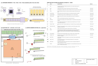
2026-10-24 6:09 PM EDT — Decision: one-row cell carrier as a nested container
the designer defined the loading scheme. The stock tray is a set of one-row cell carriers, loaded at stock-loading time, so a single tray can hold more than one component type. The one-row carrier is another nested container type. Once a part is in its carrier, it stays there until it's placed, which lets every move after loading be automatic.
Container hierarchy as of now:
- Part sits in an insert pocket sized for it.
- The insert goes into a cell, 10x10 mm or 20x20 mm, on the 10 mm grid.
- The cell goes into a one-row carrier (one row of cells).
- Carriers are loaded into the stock tray (a set of carriers), then moved into drawers in the drawer wall behind the bed (gravity detent, opened by lift-and-pull with the needle, rail built into the carrier box).
OSSO notes: the carrier's footprint becomes the common interface, so drawer, stock tray and rail details are all sized to it. Each carrier could carry a readable ID (printed code or notch pattern) so the camera knows which parts it holds. Notes only.
2026-10-24 6:18 PM EDT — Decision: QR code on each one-row carrier, stored as inventory
the designer decided each one-row carrier gets a QR code, on both its edge and its top. A loaded carrier can be stored as inventory the way a drawer is. OSSO notes: the edge code can be read while carriers stand in storage or sit in a drawer, and the top code can be read by the head camera during pickup. The QR maps to a record (component type, cell positions, quantity left), so the carrier itself is the stock unit. A small edge code limits how much data fits, so it should hold an ID that points to the record, not the data itself. On a 14K resin print the QR could be embossed or a label could be applied. Notes only.
2026-10-24 6:22 PM EDT — Decision: names for PnP part storage
the designer set these names, from smallest to largest:
- Part: the component.
- Nest: the shaped pocket the part sits in (was "insert pocket").
- Pod: holds one part, 10x10 mm or 20x20 mm on the 10 mm grid (was "cell").
- Strip: one row of pods, with a QR code on its edge and top (was "one-row carrier").
- Tray: the holder of strips inside the machine (was "stock tray").
- Matrix: the drawer wall at the back of the machine, behind the bed. It's grid-based (column/row), uses gravity detents, and opens with lift-and-pull by the needle (was "drawer wall").
- Offline drawer: where loaded strips are kept as inventory off the machine.
In short: a part sits in a nest, in a pod, on a strip. Strips are stored in an offline drawer and run from a tray or the matrix in the machine. These names replace the earlier working terms in all future notes.
2026-10-24 6:23 PM EDT — Decision: manual strip loading for offline storage
the designer decided that loading parts into strips for offline drawer storage is manual for now. A person puts each part into its nest and pod on the strip. Automated loading stays a possible later step.
2026-10-24 6:25 PM EDT — Decision: intelligent camera confirmation when strips load into the matrix
the designer wants the camera to confirm parts intelligently as strips are loaded into the matrix. OSSO notes on what it could check: read the strip's QR (top) to pull its record, then look at each pod to confirm a part is present, that it's the expected package or marking, and that its orientation and polarity are right. Any mismatch flags that pod before placement starts. This catches mistakes from manual strip loading, and it keeps the inventory record up to date. Experiment, not a red flag. Notes only.
2026-10-24 6:26 PM EDT — Decision: matrix positions chosen for PnP efficiency
the designer decided that the machine picks where each strip goes in the matrix to make PnP efficient, not so a human can find things. The QR code and the inventory record track where every strip is, so people never need to know matrix positions. OSSO notes: the machine can put frequently used or soon-to-be-placed parts in the drawers closest to the head's path, group parts by placement order to shorten moves, and reorganize between jobs. Notes only.
2026-10-24 6:45 PM EDT — Design logic review: conflicts found
the designer asked whether the design logic conflicts anywhere. OSSO found:
- Main conflict: on a bed slinger the head moves only in X and Z, while the bed carries Y. A matrix fixed to the frame behind the bed is off the head's line, and the needle can't pull a drawer forward in Y.
- Smaller tensions: (1) the gravity-detent tilt versus pods needing to sit flat and at a known height when picked; (2) the needle-as-handle loads on the B needle, its Luer and the tool-drop magnet latch; (3) whether a strip is itself the drawer or sits inside one, which decides what carries the rail; (4) where the in-machine tray sits and what it does next to the matrix.
Everything else lines up: bottom reflow first, the 10/20 mm grid, QR tracking and the camera checks.
the designer confirmed the matrix is fixed, doesn't move with the bed, and sits next to the gantry.
2026-10-24 6:45 PM EDT — Decision: two hooks, one on the bed and one on the head, open the matrix drawers
the designer chose to open drawers with existing motion. There's one hook on the bed and one on the head. The combined bed (Y) and head (X/Z) moves pull a drawer open and bring it into the head's reach. The head hook is offset from the needle, so the needle no longer works as the drawer handle. OSSO notes: this removes the drawer-drag loads from the B needle, its Luer and the tool-drop latch (tension 2), and it uses no added motors. The head hook adds a little mass to the head and has to clear the five stations, the ball hopper and C's fold. The lift-and-pull over the gravity-detent stop could come from the head hook's Z, while the bed hook supplies the long Y pull. To check: hook engagement tolerance, the order of moves to open and close, and making sure the bed can't move with a drawer half open. Experiment, not a red flag. Notes only.
2026-10-24 6:59 PM EDT — Decision: matrix stays at the back; lift latch with no actuator, opened by bump to lift
the designer kept the matrix at the back, fixed next to the gantry. He chose the non-actuator latch: the gravity detent is the latch itself. The drawer drops into a notch when it closes and opens with a bump to lift. OSSO clarified that the head moves only in X and Z, so the head hook can lift (Z) and move along X but can't pull in Y. Working sequence: (1) the head hook bumps the drawer front up with Z, out of its notch; (2) the bed hook, moving in Y, pulls the drawer forward into the head's reach; (3) the bed pushes the drawer home to close it, and gravity drops it back into the notch. No added parts, motors or magnets. To check: how much lift clears the notch, whether bed motion or vibration can unseat a drawer, and the timing hand-off between the head lift and the bed pull. Notes only.
2026-10-24 7:06 PM EDT — Snap v15
Frozen to versions/v15_2026-10-24 + versions/OSSO_v15_2026-10-24.tar.gz (the project without versions/, video/, stray root tarballs and ._* files; refs/TOOLS.md copied to the version root), same layout as v14. Since v14 (Oct 23):
- Pump: two-piston alternating FOC pump calculation (refs/two_piston_alternating_v1); observation that the pump resembles a syringe pump.
- Needles: all-metal Luer needles for consistency; 3D-printed needle tips, bonded, plus a calibration feature for zeroing tips.
- Machine: larger 300 mm bed slinger base; solder ball drop above the needle array; milestone judgment that the system is feasible.
- Soldering: TH parts placed by jig with underside solder rings; bottom reflow first (TH bodies sit on top, top reflow must navigate them); new design rule to lay out boards with reflow in mind.
- PnP part storage: naming part / nest / pod / strip / tray / matrix; 10 mm and 20 mm pods (0402 smallest part); oversize parts with a manual park spot; one-row strips as nested containers with QR codes tracked as inventory, loaded manually offline and confirmed by camera when loaded into the matrix; matrix positions chosen for PnP efficiency; matrix stays at the back of the bed, drawers opened by a head hook and a bed hook, gravity lift latch with no actuator.
- New drawing: drawings/osso_part_storage_v1.png / .pdf.
The docs site now lists v15, and site builds now scrub personal details from generated output. Mac sync excludes versions/ and video/ as before.