New in this snapshot: 12 drawings, 8 STEP files, 0 documents/media.
2026-10-19 4:00 PM ET — DECISION (the designer): mains companion uses a 5.08 mm (0.200 in) grid
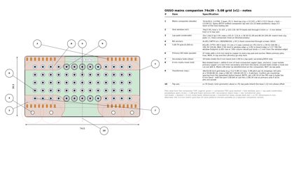
- The first mains/transformer companion uses a 5.08 grid, not 5.0, so US/inch-grid transformers fit. The CL2-5.0R-12 drawing shows 5.08 pitch.
- The 5.0 mm metric grid is still possible as an alternate companion variant.
- Board: double-width 74x39 (host top v1g x 33–107, y 94.5–133.5). It solders to both lap-pad sets, with 4 M2 anchors.
- TH grid: 65x Ø1.3 PTH / Ø2.5 land (2.58 mm web), 13 cols x 5 rows centred on (70,116.5): x 39.52–100.48, y 106.34–126.66. That fills the window footprint. Lands are at least 2.09 from the window edge (R5 corners included) and 5.27 from the board edge. A 6th row or 14th column would leave lands closer than 1 mm to the window.
- 6 mm moat: 47 holes are primary-OK, meaning at least 6 mm land-to-copper from every lap pad and anchor (host-connected = SELV). The other 18 sit in the band, at minimum 2.69 mm to a lap pad, and are for secondary use only.
- In the end rows (y 106.34 and 126.66), only x 59.84–75.08 are primary-OK. It isn't symmetric, because the lap pads carry the base's 1.22 mm phase offset.
- Mains L/N come in by wire or terminal on the companion, never through the lap pads.
- The representative transformer has 2x5 pins at x 59.84–80.16, rows 20.32 apart. Pin x 80.16 in each end row falls inside the band. A real part has to shift 5.08 left, or have no primary pin there. Confirm pin count and row spacing from the CL2 datasheet.
- Files: cad/top_middle_v1g/make_top_v1g_mains_508.py (v1g originals kept) produces OSSO_companion_mains_double_74x39_508_board.step and OSSO_top_v1g_with_mains_companion_508.step. Hole data: mains_companion_508_geom.json. Drawing: drawings/mains_companion_508_v1.py → osso_mains_companion_508_v1.png/.pdf.
2026-10-19 4:25 PM ET — Mains companion: partitioning and build order
the designer test-fit the CL2-5.0R-12 (example part, needs 6 columns) on the 5.08mm mains companion; it fits. The 6mm mains spacing is a per-design layout rule chosen by the builder, not a fixed zone. the designer likes that the transformer/mains companion can be prepared (built and tested) first, then mounted onto the top board.
2026-10-19 4:35 PM ET — Companion strategy: one size, many drill patterns
After checking the Hammond 162/164 (A = 0.25/0.30/0.40in by size; only some land on 2.54/5.08), the designer decided: keep the unified companion size, but design multiple companion drill patterns — exact footprints for target parts plus extra general pads to cover the long tail of components. The generic 5.0/5.08 grids become examples, not the only option.
2026-10-19 6:55 PM ET — PSU fit study v1 (linear AC-DC on the 74x39 mains companion)
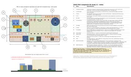
the designer asked whether a basic linear supply fits on the double-width mains companion with the 5.08 grid. Drawing: drawings/psu_companion_fit_v1.py → psu_companion_fit_v1.png/.pdf (parts JSON written next to it). STEP: cad/top_middle_v1g/OSSO_top_v1g_with_mains_companion_508_psu.step (34.1 MB, reimports valid, top of the parts 21.7 above host L1), script make_top_v1g_psu.py. Part bodies are typical datasheet envelopes, not verified; the Hammond 162/164 table is from the hammfg.com datasheet.
Verdict: the plan view fits a ≤ ~5 VA supply. Height is the limit.
- Parts and positions:
- T1: low-profile EI30-class transformer (CL2-class), ≤ 32.0x27.5 body, 2x6 pins at x 64.92–90.32, rows y 106.34 (SEC) and 126.66 (PRI).
- J1: 2-pos 5.08 mm terminal at (39.52/44.60, 121.58), wires exit toward the top edge.
- F1: TR5 fuse at (54.76/59.84, 121.58).
- C1: X2 cap, 10 mm pitch, at (39.52/49.68, 116.5). Optional.
- RV1: 5 mm MOV at (44.60/49.68, 111.42).
- D1: MB10S SMD bridge.
- C3: 1000 µF 25 V, 12.5x20, at x 100.48.
- U1: SOT-223 regulator, with C4/C5 on the SMD strip at the bottom of the companion.
- DC leaves through the right lap pads.
- Part bodies use 1383 mm², 48% of the board. The primary wing (x 33–62) is full.
- Spacing: PRI to SEC is 13.6 min; PRI to the low-voltage lap pads and anchors is 7.77 min (≥6 required).
- T1's PRI pins must sit at x ≤ 75.08. The other PRI-row pins at x 80.16–90.32 must be NC with no copper.
- Don't fit: a 5x20 holder, a 10 mm MOV, a KBP/GBU bridge, or 2200 µF 16x25 (25 + 1.7 > 26).
Heights.
- From the journal: 150 cube − 124.0 (10-board stack) = 26 above the top board. Parts on the companion start 1.7 higher, so 24.3 is available, or 22.3 with an assumed 2 mm lid.
- Hammond 162/164 (L x W x H, mm):
| Size |
VA |
Dims |
Fits |
| D |
1.1 |
35.1x28.7x23.8 |
10 boards only with zero lid margin |
| E |
2.4 |
35.1x28.7x30.2 |
9 boards or fewer |
| F |
6 |
41.4x33.3x33.3 |
9 boards or fewer (overhangs the companion 1.2 per side) |
| G |
12 |
47.8x39.6x38.1 |
8 boards or fewer, plus too deep for the companion |
| H |
20 |
57.1x47.8x36.6 |
8 boards or fewer, plus too deep for the companion |
- Hammond pin pitch is 0.25/0.30 in, which is not on the 5.08 grid. The row spacing (1.20–1.60 in) is wider than the 27 mm window unless the part is rotated and given custom holes.
- Bottom-board use: needs feet at least as tall as the tallest part + 1.7, about 21.7 here. With 10 boards the 150 cube leaves 26 TOTAL for feet plus top-board parts. Space below the stack is not defined in the journal. The transformer's weight hangs on the solder joints, so use the M2 anchors plus body screws.
Recommendations.
- Keep the mains parts, transformer and rectifier on the companion.
- Put the regulator as a D2PAK on the host's SMT-3R pad (copper as heatsink), fed through the right lap pads. Put larger bulk capacitance (2x 1000 µF 12.5x20, or a low-profile 16x20) on the host grid. SMT-3R is too small for D2PAK plus a 12.5 mm can.
- Transformers above ~5 VA need a 9- or 8-board stack, or a taller enclosure.
2026-10-19 7:40 PM ET — DECISION (the designer): enclosure and stack height are per-build, not fixed
- The 150 mm cube and the 10-board stack are NOT system constraints. A stack can be 3 boards with tall top components, or taller than 10. Headroom above the top board (and feet below a bottom board) is set per build.
- Earlier height verdicts tied to "26 mm over a 124 mm stack" (top v1a, PSU fit v1) were illustrative only. Fit studies now check plan view, the 6 mm mains spacing and mechanical support.
2026-10-19 7:47 PM ET — PSU companion fit study v2 (no height limit)
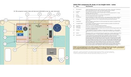
- drawings/psu_companion_fit_v2.py → .png/.pdf/.json; cad/top_middle_v1g/OSSO_top_v1g_with_psu_companion_psu_v2.step (33.4 MB, valid, reimported, bbox 140x140.37, z −1.5…41.4).
- Constraints: plan view only (74x39 companion, 74x27 window), ≥6 mm primary-to-low-voltage lap/anchor copper, mechanical support.
- Hammond 162/164: D/E fit easily; F 6 VA fits inside the companion+host with a full 5x20 holder; G 12 VA fits (0.4 mm past host edge, body screws drilled Ø3 through companion+host); H 20 VA = max (5.1 mm overhang, all secondary parts on host); J 36 VA fails (30.48 row span > 27 window).
- Pin pitches are off the 5.08 grid for F/G/H → PSU companion uses custom holes.
- Recommended R1 = Hammond G: primary wing J1/F1 5x20/C1 X2/RV1 10 mm; KBP bridge on companion; C3 2200µF 16x25, U1 TO-220+HS, C4 on host. PRI–host min 6.13, PRI–SEC 33.31.
- Overhang onto the top board is allowed: bodies 1.7 above host L1, so host parts under them must be ≤1.5 tall. Anchors under the body need countersunk M2; hanging use needs anchors + body screws.
2026-10-19 7:59 PM ET — DESIGN RULE: companions are standalone-testable
- Every companion must be testable on its own, without the base/top board: all parts of its function live on the companion, with test access for input and output (terminals/test points), and it must sit stably on its own (feet/standoffs).
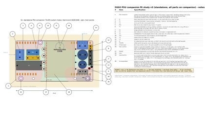
2026-10-19 8:09 PM ET — PSU companion fit study v3 (standalone, all parts on companion)
- drawings/psu_companion_fit_v3.py → .png/.pdf/.json; cad/top_middle_v1g/make_top_v1g_psu_v3.py → OSSO_psu_companion_standalone_psu_v3.step (2.45 MB, 181 solids, valid) and OSSO_top_v1g_with_psu_companion_psu_v3.step (33.75 MB, 2754 solids, valid, bbox 140x140, z −1.5…33.5).
- Constraints: all PSU parts inside 74x39, nothing on host, no overhang, full-size parts, no height limit, TH leads only in 74x27 window, 6 mm PRI to laps/anchors.
- Result: max 2.4 VA = Hammond 162E/164E (D 1.1 VA same footprint). F/G/H: body L 41.4/47.8/57.1 > 39. J: row span 30.5 > 27. EI38/13.6, EI38/16.5 (6 VA), EI42/14.8: PRI row span 20 > 18.72 lap-free gap (5.36 mm moat, rejected). EI48: too big.
- Parts: T1 162E, J1 2-pos 5.08 mains, F1 5x20 holder, C1 X2 0.1µF, RV1 10 mm MOV, D1 KBP206G, C2 1000µF 35V Ø10x20, U1 TO-220 + HS1 13x6.5, C4 220µF Ø8, C5 0.1µF, J2 2-pos 5.08 DC out, TP1 VRAW, TP2 0V.
- Numbers: PRI–laps min 6.05, PRI–SEC 27.98, PRI–PRI 1.75 (functional); body area 1801 mm² (62%); tallest 30.2 mm; mass ≈152 g.
- Feet: nylon M2 standoffs at anchors (38,97.2),(102,97.2) + new Ø2.2 hole F3 (56.6,132.0) + B1 Ø8 adhesive bumper under T1 (75.3,128). Tripod alone 1.9 mm tip margin → B1 needed (8.4 mm).
2026-10-19 8:22 PM ET — Request: top v1h (bigger dual companion/window, TH grid dropped around C/C')
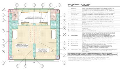
- the designer: drop the TH grid around fiducials C/C', enlarge the dual companion window/slot area and outline; lap-pad count/pitch and anchors unchanged; fiducials and their keep-outs do not move.
2026-10-19 8:36 PM ET — top v1h + PSU companion fit v4
- drawings/top_v1h.py → osso_top_v1h.png/.pdf + top_v1h_geom.json (v1g files kept).
- Dual companion 74x39 → 89x45.5 R1.5: x 25.5–114.5, y 94.5–140 (top flush with the board edge, like the single companions). 3x6 clearance slot over the tool slot.
- Window, as a union of shapes:
- main 89x27 R5, x 25.5–114.5, y 103–130 (still bounded by the lap rows);
- centre tab 30x30.5 R2, x 55–85, y 101.5–132, between the lap sets;
- two wings 7.5x36.5 R2, x 25.5–33 / 107–114.5, y 96–132.5.
- Clearances: window and companion 1.0 to the C/C' Ø5 keep-outs; tab 1.04 to the top crossbar and 2.0 to the tool slot; wings 1.0 to the ring band and laps; window 7.1 to the pogo pads; companion 0.14 to the pogo box (as v1g); pin-1 6.5; clamp 14.
- Lap pads (32 @ 2.54), the 4 M2 anchors, fiducials, slots, pogo pads and strip unchanged.
- Grid 1194 → 1028 holes: −190 (96 C/C' zones, 74 window, 20 under the companion); +24 restored (SMT-3/2T trims).
- SMT-3 narrowed 23 → 15.5 wide (x 9–24.5 / 115.5–131). SMT-2T shortened to y 95.86–100.5.
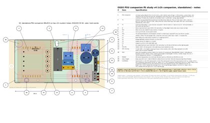
- PSU v4 (drawings/psu_companion_fit_v4.*, same rules as v3), max 8 VA:
- EI42/20.5 fits (EI42/14.8 5 VA and EI38/16.5 6 VA also fit). Hammond best is F 6 VA; G and larger are too long (47.8 > 45.5). EI48 does not fit.
- Layout: T1 on the left, PRI row x 60.03. The primary parts (F1 5x20, J1, RV1, C1) sit in the centre tab and the lap-free band. Secondary on the right: HS1 13x19, U1 TO-220, C2 3300µF Ø12.5, D1 KBP, C4 220µF, C5 1206, J2, TP1–3. SEC crossing is 2 traces at y 95.2/99.2.
- Spacing: PRI to laps/anchors 6.49, PRI–SEC 11.2, PRI–HS 6.25. Body area 2671 mm² (66%). Tallest part 38 mm. Mass ≈316 g.
- Feet: nylon standoffs at anchors 38/102 + 2 bumpers at the top corners; tip margin 19 mm.
- STEPs in cad/top_v1h/ (make_top_v1h_psu_v4.py), both valid on reimport:
- OSSO_psu_companion_standalone_v1h_psu_v4.step: 2.5 MB, 184 solids;
- OSSO_top_v1h_with_psu_companion_v1h_psu_v4.step: 29.8 MB, 2425 solids.
2026-10-19 8:40 PM ET — Feasibility mark: 8VA PSU companion; Version 7 frozen
the designer set the feasibility mark: the v1h dual companion (89x45.5) can hold a full standalone 8VA linear power supply (EI42/20.5 class, full-size parts, 6mm mains spacing). Going forward, the PSU layout geometry is NOT carried into the design; it only established the max. Top board continues from v1h geometry without PSU-specific features. Frozen as versions/v7_2026-10-19 plus OSSO_v7_2026-10-19.tar.gz (video excluded).
2026-10-19 8:41 PM ET — Design rule: on-board PSU limit
Anything larger than 8VA uses a dedicated external power supply, not an OSSO companion.