← v13 v15 →
v14: Tool drop needle-retract mechanism: 60 psi sweep, magnet hold study, v2d EPM latch drawing and CAD model with fit check, TOOLS.md update
Frozen Fri Oct 23, 2026, 10:42 AM ET · 1002 files · folder: versions/v14_2026-10-23/ · archive: OSSO_v14_2026-10-23.tar.gz
What changed
- 2026-10-21 2:14 PM EDT — POC v3: stack the discs, set the gap with the hold-down screws
- 2026-10-21 2:16 PM EDT — Solder application roadmap: Kapton stencil first, ball tinning later
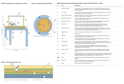
- 2026-10-21 2:41 PM EDT — Ball dispenser POC v4: chute alignment fix + external BR-G1 drive gear (the designer's request)
- 2026-10-21 5:03 PM EDT — Flux head serves two steps
- 2026-10-21 5:15 PM EDT — Post-reflow screen ahead of test
- 2026-10-21 5:18 PM EDT — Purpose of solder ball drop (reminder)
- 2026-10-21 5:20 PM EDT — Tinning enables pre-inspection and prep ahead
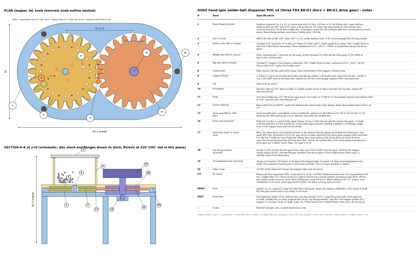
- 2026-10-21 9:52 PM EDT — Ball dispenser POC v5: two part types (BR-G2 FR4 carrier, BR-C1 stainless covers), printed D-spindle (the designer's request)
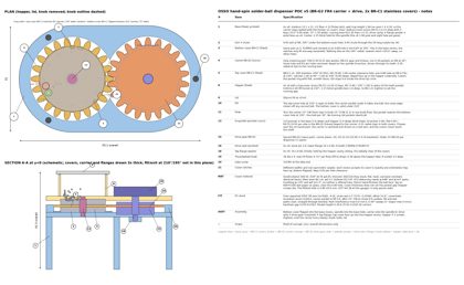
- 2026-10-21 10:05 PM EDT — BR-C1 cover v2 for SendCutSend (304 SS .030", as cut, Ø0.80 hole)
- 2026-10-21 10:19 PM EDT — BR-C1 v2 covers ordered
- 2026-10-22 9:29 AM EDT — XYZ head concept: folding tools (ideation)
- 2026-10-22 9:31 AM EDT — Ball drop exits through a Luer needle (ideation)
- 2026-10-22 9:31 AM EDT — Air puff seats the ball (ideation)
- 2026-10-22 9:32 AM EDT — Shared vacuum/pressure utility (ideation)
- 2026-10-22 9:33 AM EDT — Folding enables per-deploy Z calibration (ideation)
- 2026-10-22 9:35 AM EDT — Flux reservoir rides on the head (ideation)
- 2026-10-22 9:36 AM EDT — Solder ball reservoir rides on the head (ideation)
- 2026-10-22 9:36 AM EDT — Cleaner delivered by hose (ideation)
- 2026-10-22 9:37 AM EDT — Air dry after clean (ideation)
- 2026-10-22 9:38 AM EDT — Design note: farm model (high level)
- 2026-10-22 9:40 AM EDT — Reflow: heated bed + hot-air Luer needle (ideation)
- 2026-10-22 9:42 AM EDT — Laser integration: gantry runs under the galvo (ideation)
- 2026-10-22 9:47 AM EDT — Single-machine scope decisions (ideation)
- 2026-10-22 9:50 AM EDT — Solder is applied as preforms (ideation)
- 2026-10-22 9:55 AM EDT — Cost comparison basis: high volume (decision)
- 2026-10-22 9:56 AM EDT — Parts tray setup is a separate station (ideation)
- 2026-10-22 9:56 AM EDT — Kit loads with the blank (ideation)
- 2026-10-22 9:57 AM EDT — Job order: laser the bottom first, then flip (ideation)
- 2026-10-22 9:58 AM EDT — Two job types: bottom and top (decision)
- 2026-10-22 9:59 AM EDT — Bottom and top jobs can run on different machines (decision)
- 2026-10-22 10:02 AM EDT — Concept drawings: single-machine cell + process flow (the designer's request)
- 2026-10-22 10:59 AM EDT: Cell size TBD; machines as a possible business line
- 2026-10-22 11:02 AM EDT: Tool-drop actuation and lock options
- 2026-10-22 11:05 AM EDT: Concept drawing: pneumatic tool drop (Option A)
- 2026-10-22 11:08 AM EDT: Tool drop drawing: part sources
- 2026-10-22 11:12 AM EDT: Cleaning needle is the base tool for the first tool-drop prototype (decision)
- 2026-10-22 11:14 AM EDT: Concept drawing: cleaning-needle tool-drop PoC
- 2026-10-22 1:48 PM EDT – Tool drop mechanical PoC v1 (CadQuery)
- 2026-10-22 1:53 PM EDT: Tool-drop PoC build added to TODO
- 2026-10-22 1:56 PM EDT: Purpose of the mechanical tool-drop test
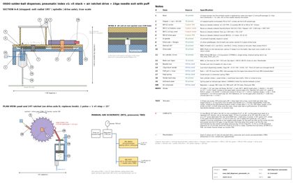
- 2026-10-22 2:59 PM EDT – Ball dispenser pneumatic index v1 drawing
- 2026-10-22 5:17 PM EDT: Pneumatic ball dispenser ratchet decision
- 2026-10-22 5:27 PM EDT – Ball dispenser pneumatic index v1 CAD
- 2026-10-22 5:33 PM EDT – Tool-drop mech PoC motion sequence annotation
- 2026-10-22 5:52 PM EDT – Tool-drop mech PoC v1: linkage past dead center at folded rest (CAD not changed)
- 2026-10-22 6:52 PM EDT – Tool-drop mech PoC v2 (option B) and kinematic checks
- 2026-10-22 7:46 PM EDT – Tool-drop v2b: torsion return spring and side detent
- 2026-10-23 7:35 AM EDT: Tool drop v2c notes (guide bearings for the pistons)
- 2026-10-23 7:40 AM EDT: Tool drop v2c direction: single double-acting piston, 30 psi design point
- 2026-10-23 7:43 AM EDT: Design note: all metric, minimize fastener sizes
- 2026-10-23 7:44 AM EDT: Design note: fasteners limited to M5 and M3
- 2026-10-23 7:44 AM EDT: Design note: exceptions to the M5/M3 rule
- 2026-10-23 8:02 AM EDT: Tool drop v2c concept drawing v1 (drawing only)
- 2026-10-23 8:25 AM EDT: Tool drop v2c pressure sweep (calculation only, refs/tool_drop_pressure_sweep_v1.md/.png)
- 2026-10-23 8:29 AM EDT - Tool drop: 60 psi set, plunger elimination
- 2026-10-23 8:30 AM EDT - Tool drop: over-center toggle chosen
- 2026-10-23 8:49 AM EDT - Tool drop: over-center toggle check result
- 2026-10-23 9:01 AM EDT - Tool drop: digital-control magnet hold
- 2026-10-23 9:22 AM EDT - Tool drop: magnet hold sizing (calculation and research, no drawing/model)
- 2026-10-23 9:27 AM EDT - Tool drop: magnet hold sizing result and Plan B decision
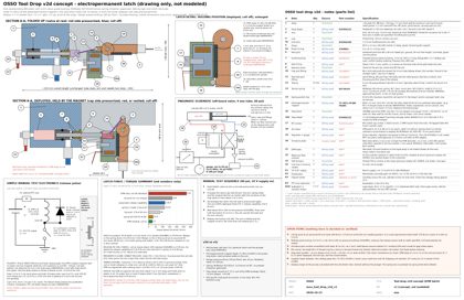
- 2026-10-23 9:45 AM EDT - Tool drop v2d concept drawing delivered (drawing only, not modeled)
- 2026-10-23 10:42 AM EDT - Tool drop v2d CAD model (cad/tool_drop_mech_poc_v2d)
- 2026-10-23 10:42 AM EDT - VERSION v14 snapped
New in this snapshot: 32 drawings, 140 STEP files, 13 documents/media.
Key decisions
Drawings new in v14
Other images
STEP files (202)
Documents & media
Tools snapshot
Source: versions/v14_2026-10-23/refs/TOOLS.md
Tools used as of this version
OSSO tools inventory
Software, libraries, file formats, techniques and services actually used on OSSO, found from the scripts in cad/, drawings/, pcb/, fab/, laser-test/, site_build/, the installed environments (/workspace/.cadvenv, system packages) and JOURNAL.md. Versions are what is installed on the box as of 2026-10-23. Two box venvs exist: /workspace/.cadvenv (older) and /workspace/.cadenv (CadQuery 2.8.0 + pyvista + trimesh, used for the tool-drop v2d model). "Not installed now" means a past script used it but the current box env lacks it.
CAD generation (3D)
| Tool |
Version |
Used for |
First used/Files |
Python (venv /workspace/.cadvenv) |
3.13.5 |
Runs every generator and verifier script |
Oct 14; all *.py |
| CadQuery |
2.8.0 |
Parametric solids for jigs, boards, stencil frames, dispenser POCs; STEP/STL export (cq.exporters.export), STEP re-import (cq.importers.importStep) |
Oct 16, cad/jig_v4b/jig_v4b.py; all cad/*/make_*.py |
| OCP (cadquery-ocp, OpenCASCADE bindings) |
7.9.3.1.1 |
Low-level B-rep work: BRepCheck_Analyzer validity, volume props, booleans |
cad/*/verify*.py, dispenser POC v3-v5 |
| numpy |
2.5.4 |
Geometry math (involute gear profiles, hole patterns, sweeps) |
most CAD/drawing scripts |
| shapely |
2.2.0 |
2D outlines, morphological closing, unary_union for gear/disc profiles |
pcb/br_g1_v1/make_br_g1.py, laser profiles |
| scipy |
1.18.1 |
Installed CadQuery dependency; numeric helpers |
venv |
| casadi / nlopt |
3.8.1 / 2.11.0 |
CadQuery solver dependencies (assemblies/sketch constraints) |
venv |
| vtk |
9.6.2 |
CadQuery visualization backend |
venv |
pyvista (venv /workspace/.cadenv) |
0.49.1 |
Offscreen preview renders of STL/STEP models (iso, close-up, section views) |
Oct 16-19, versions/v5_2026-10-19/cad/*/render.py; Oct 23, cad/tool_drop_mech_poc_v2d/render_preview.py |
| trimesh |
5.1.1 (venv /workspace/.cadenv) |
STL watertight/extent checks |
cad/stencil_v1/verify.py |
Fit check / interference method
| Tool |
Version |
Used for |
First used/Files |
CadQuery/OCC boolean intersect + Volume() |
2.8.0 / 7.9.3 |
Pairwise intersection volume between parts re-imported from the exported STEP; 0 mm³ = no interference |
Oct 21, cad/ball_dispenser_poc_v3..v5 |
OCC BRepExtrema_DistShapeShape |
7.9.3 |
Minimum clearance between non-touching parts at each sweep state (bbox prefilter first); an explicit list of intended contacts is excluded |
Oct 23, cad/tool_drop_mech_poc_v2d/ |
| Mechanism torque/force sweep |
(technique) |
Moment arm sign and size, dead-center margin, deploy/release/hold margins at mu 0.2 / 0.3 / 1.5x seal friction, pass/fail gate in fit_check.json |
Oct 23, refs/tool_drop_*, cad/tool_drop_mech_poc_v2d/ |
| Angular sweep |
(technique) |
Rotate moving parts in 2° steps (0-20°/0-30°), re-check intersection volume and minimum gap at each step (gear mesh backlash 0.035-0.037) |
POC v4/v5 |
| Probe cylinders |
(technique) |
Thin cylinders along fill/exit axes intersected with exported disc STEPs to prove paths open or blocked; hole-axis alignment asserted to 0.000 |
POC v4/v5 |
| Tolerance-case matrix |
(technique) |
All thickness combinations (e.g. 0.25/0.30 carrier, 0.711-0.813 cover) checked for pocket gap and overlap |
POC v3-v5 |
| STEP re-import + validity |
(technique) |
Every exported STEP re-read, solids counted, isValid(); STLs watertight |
Oct 16 jig v4b onward |
Drawings and 2D
| Tool |
Version |
Used for |
First used/Files |
| matplotlib |
3.11.2 |
All engineering drawings (plan, section, exploded) to PNG and multi-page PDF (PdfPages) |
Oct 15; drawings/*.py |
| ezdxf |
1.4.5 |
DXF cut profiles (laser tests, alignment patterns, BR-G1 laser, BR-C1 covers) |
laser-test/gen.py, cad/laser_align_*, br_c1_v2.dxf |
| SVG (hand-written) |
(format) |
Laser test/alignment patterns for LightBurn |
laser-test/*.svg, cad/laser_align_*/*.svg |
| Pillow |
12.3.0 (system) / 13.0.0 (venv) |
Site thumbnails, image compositing |
site_build/build_site.py |
| fontTools, kiwisolver, contourpy, pyparsing |
4.67.0 / 1.5.1 / 1.4.0 / 3.3.3 |
matplotlib dependencies |
venv |
PCB: KiCad, Gerber, drill, DRC
| Tool |
Version |
Used for |
First used/Files |
| KiCad / kicad-cli |
9.0.2 |
.kicad_pcb written by script, then kicad-cli exports Gerbers, Excellon drill, job file, and runs DRC (drc.rpt, 0 errors) |
Oct 21, pcb/br_g1_v1/make_br_g1.py, pcb/br_g2_v1/ |
| Hand-written RS-274X X2 + Excellon |
(technique) |
First Gerber set before KiCad was on the box |
Oct 16, fab/gen_v3b_gerbers.py |
| gerbv |
2.10.0 |
Render Gerbers back to PNG for visual check |
Oct 16, fab/render/, pcb/br_g1_v1/preview_gerbv.png |
| Gerber/Excellon re-parse verifier |
(technique) |
Re-read output files, count teeth/holes, compare to geometry report |
pcb/br_g1_v1/verify_br_g1.py, verify_report.json |
3D printing and laser
| Tool |
Version |
Used for |
First used/Files |
| Bambu Studio (AppImage, headless slice) |
02.08.02.61 (box); the designer 02.08.02.60 |
3MF projects for P1S, headless slice estimates |
Oct 16, cad/jig_v4*/make_3mf.py, /workspace/tools/bambu |
| LightBurn |
the designer's copy |
UV galvo laser jobs from SVG/DXF |
Oct 16, laser-test/settings.md, refs/laser/ |
| Klipper (Elegoo Neptune 4) |
stock |
Planned PnP / flux syringe motion |
Oct 21, journal |
File formats
| Format |
Tool |
Used for |
First used/Files |
| STEP (.step) |
CadQuery/OCC |
Parts and assemblies for the designer's CAD and vendors |
Oct 16, cad/*/*.step |
| STL |
CadQuery |
Print meshes |
Oct 16, cad/jig_v4b/*.stl |
| 3MF |
make_3mf.py |
Bambu Studio projects |
Oct 16, cad/jig_v4b/*.3mf |
| DXF / SVG |
ezdxf / script |
Laser and SendCutSend cut files |
Oct 15, laser-test/, br_c1_v2.dxf |
| Gerber X2, Excellon, .gbrjob, zip |
kicad-cli / script |
PCB fab uploads |
Oct 16, fab/, pcb/*/gerbers |
| PNG / PDF |
matplotlib |
Drawings |
drawings/ |
| JSON / Markdown |
Python |
Geometry/verify reports, notes, journal |
throughout |
| MP4 |
(video generation) |
Vision reels |
Oct 15, video/ |
PDF tools
| Tool |
Version |
Used for |
First used/Files |
| matplotlib PdfPages |
3.11.2 |
Multi-page drawing PDFs, tech sheets |
drawings/*.pdf, refs/laser/laser_tech_sheet.pdf |
| poppler-utils (pdftoppm, pdftotext, pdfunite) |
25.03.0 |
Rasterize/read PDFs (datasheets, checks), merge pages |
refs/ datasheets |
Docs site
| Tool |
Version |
Used for |
First used/Files |
| build_site.py (custom static generator) |
in repo |
Builds site/ from JOURNAL.md, TODO.md, PENDING, refs, versions |
Oct 20, site_build/build_site.py |
| Python-Markdown (extra, sane_lists) |
3.11.1 (system) |
Markdown to HTML |
build_site.py |
| check_links.py |
in repo |
Verifies every relative link and anchor |
site_build/check_links.py |
Versions, sync and backup
| Tool |
Version |
Used for |
First used/Files |
| GNU tar + gzip |
1.35 |
Version snapshots versions/OSSO_vN_DATE.tar.gz; sync bundles |
Oct 15, versions/ |
| sha256sum / split (coreutils) |
9.7 |
Chunked tar transfer to the designer's Macs with checksum verification (hourly sync) |
Oct 21 restore from work Mac copy |
| Google Drive mirror |
(connector) |
Daily mirror of the project, done by another assistant |
daily |
| ffmpeg |
7.1.5 |
Video/media handling |
video/ |
Research and fab services
| Service |
Version |
Used for |
First used/Files |
| Web research (search + fetch) |
live |
Vendor specs and prices |
throughout |
| PCBWay |
web |
Blank v3b (5 pcs ENIG), 5 OSSO boards, 50 BR-G1 discs; laser-cut tolerance check |
Oct 16, fab/, pcb/br_g1_v1/README_FAB.md |
| SendCutSend (site + spec API scs-specs-platform) |
web |
304 SS .030" limits; BR-C1 v2 covers ordered; Oct 23: 1008 CRS .074" armature plate for the tool-drop EPM latch (DXF) |
Oct 21, cad/ball_dispenser_poc_v5/br_c1/QUOTE_NOTES.md |
| Chip Quik |
web |
SAC305 ball/paste pricing for per-board solder cost |
Oct 21, journal |
| LCSC |
web |
Pogo pin YZD0029 datasheet drawing |
Oct 16, cad/pogo_YZD0029/ |
| eBay (NV Liquidation) |
web |
2x Neptune 4 parts units |
Oct 21, journal |
| Literature (DOI) |
web |
EPTC 2012 tacky flux ball attach; IRJMETS flip chip flux |
Oct 21, journal |
AI assistant
| Tool |
Version |
Used for |
First used/Files |
| OSSO assistant in the Grok Bot app |
app |
All scripting, CAD, drawings, fab files, site and journal, with background helper agents for parallel tasks |
Oct 14 onward |
Journal entries in this version
2026-10-21 2:14 PM EDT — POC v3: stack the discs, set the gap with the hold-down screws
the designer decided to stack the three BR-G1 discs directly in POC v3 and adjust the running gap by tightening the hopper's M2 hold-down screws until the middle disc turns freely. The kapton shim is a fallback only, used if the stack binds or rattles. A 0.25mm-thick disc isn't a problem, because a 0.25mm ball then sits flush and still can't pick up a second ball.
2026-10-21 2:16 PM EDT — Solder application roadmap: Kapton stencil first, ball tinning later
the designer confirmed two solder application paths. Initial: a laser-cut Kapton paste stencil (stencil v2 track), ready to try once the laser is set up and aligned. Later: ball tinning, which is flux dots from the syringe head, then 0.25mm SAC305 balls from the BR-G1 dispenser, then reflow. It comes after the dispenser POC and flux head are proven. Both paths end in the same state, a board ready for flux and part placement, so the downstream steps (part tray, PnP, reflow, test) don't change between them.
2026-10-21 2:41 PM EDT — Ball dispenser POC v4: chute alignment fix + external BR-G1 drive gear (the designer's request)
- New
cad/ball_dispenser_poc_v4/ (script make_ball_dispenser_poc_v4.py; v3 left as is) + drawing drawings/ball_dispenser_poc_v4.png/.pdf.
- Bug (the designer's section of the v3 assembly STEP: the drop chute looked like it sat on a pin-like feature). Measured from the exported STEP (the designer's Downloads copy and the box re-export): chute axis (-7.7274, 2.0706) = R8 @165°, and the bottom-disc pocket was at the same XY (0.000 error). But the bottom disc is clocked +15°, so its R3 Ø0.80 pin hole (150°+15°) also sat on the 165° radial, at (-2.8978, 0.7765). It is the same Ø0.80 as the chute relief bore, and at rest the middle-disc web caps the Ø0.30 pocket. So any section through the chute showed it lined up with a pin hole. Root cause: the exit station was picked on a radial shared with a non-pocket hole. Fix: fill moved to 210° (top hole) and exit to 195° (bottom hole), which is 30° from every bottom pin/home hole. v4 asserts alignment from the exported geometry: hole axes for every disc, and probe cylinders along the fill and chute axes through the exported disc STEPs.
- Drive gear (the designer): a 4th BR-G1 (same part, unmodified) meshes with the middle disc at +X, CD 22.10 (22.00 + 0.10 backlash for the ±0.1-0.2 routing tolerance), in the middle plane. It rides on a printed D-axle: pivot pin, 16 dia lower flange, and a 2.90 D-shaft with R0.55 corners (0.05/side in the gear D-bore). A printed 16 dia top flange washer sits on top, and an 18 dia knurled knob sits above the hopper lobe. Base and hopper grew a closed lobe (overall 53.1 x 31 x 41.3) with a 3rd M2 screw. The finger window is gone; only the knob is exposed.
- Fixed-disc teeth: file 3 teeth flush to root on each fixed disc (top 0/16.4/343.6°, bottom 15/342.3/358.6° as assembled), leaving 19 keyed teeth each. Unfiled, a fixed disc that drifted into the drive plane would overlap the drive tip circle by 3.1 mm3, and the drive would lock. Filed, the gap is 0.52 even in the drive plane.
- Fit check: 0 interference at rest. Mesh sweep 0-30° (middle CW, drive CCW, 2° steps): 0 mm3, tooth gap 0.035-0.037. Drive parts are clear of the fixed parts at all angles. All 8 thickness cases (0.25/0.30) work: pocket 0.30-0.35, drive/middle face overlap ≥ 0.20.
2026-10-21 5:03 PM EDT — Flux head serves two steps
Decision (the designer): Keep selective flux. Whole-board flux was rejected because it means too much cleanup. The flux syringe head is needed twice: (1) a dot on each pad before solder ball tinning, and (2) a dot on each tinned pad before pick and place, to hold parts and wet the reflow. the designer plans a bench test of the manual ball dispenser with a flux dot to observe the physics: bounce, self-centering, and the dot size limit before bridging. References: EPTC 2012 tacky flux ball attach (doi 10.1109/eptc.2012.6507169), IRJMETS flip chip flux (doi 10.56726/irjmets33583).
2026-10-21 5:15 PM EDT — Post-reflow screen ahead of test
2026-10-21 5:18 PM EDT — Purpose of solder ball drop (reminder)
the designer: The goal of solder ball dropping is selective solder application with no stencil. Each one-off PCB skips making a stencil and spreading paste. Part of the per-board ball upcharge is the price of that stencil-free precision on one-off boards. It does not mean matching paste volume. Balls per pad are sized for a good joint on that pad (1 for small pads, more for large or stressed joints), to be confirmed by bench test.
2026-10-21 5:20 PM EDT — Tinning enables pre-inspection and prep ahead
the designer: Ball-drop tinning removes the stencil step (wasteful, a hassle, and a time saver once automated). Tinned boards can be automatically inspected (camera check of solid, domed pads, no bridges) and prepped ahead of time: tin a batch, inspect, and store until assembly. Defects are caught before parts are placed.
2026-10-21 9:52 PM EDT — Ball dispenser POC v5: two part types (BR-G2 FR4 carrier, BR-C1 stainless covers), printed D-spindle (the designer's request)
- New
cad/ball_dispenser_poc_v5/ (make_ball_dispenser_poc_v5.py, reusing the v4 code; v4 left as is), drawing drawings/ball_dispenser_poc_v5.png/.pdf, BR-G2 fab files in pcb/br_g2_v1/, BR-C1 laser files in cad/ball_dispenser_poc_v5/br_c1/.
- BR-G2 is BR-G1 (m1 z22 gear, D-bore 3.00/2.50 R0.5, 12x Ø0.30 on R8) with the home hole and the 3 R3 pin holes removed. It is used as the carrier and as the drive gear (CD 22.10, v4 axle, flanges and knob). KiCad DRC shows 0 errors, and a Gerber/Excellon re-parse confirms 22 teeth and exactly 12 holes.
- BR-C1 is a 0.30 304 stainless disc, OD 19.00, with a Ø3.40 shaft clearance hole, one Ø0.60 hole on R8 at 210° (own frame), and OD notches 1.00 at 90° and 1.60 at 330° (0.60 deep). It is used twice. The top cover sits face up, so its hole is the fill at 210°. The bottom cover is flipped and clocked +45°, so its hole is the exit at 195° (notches 315°/75°). Unequal widths and non-symmetric angles mean each printed recess (keys 0.05/side) accepts its cover in one orientation only; this is asserted. The cover OD is 0.60 inside the drive tip circle and 4.6 from the drive flanges.
- Shaft: a printed D-spindle through the stack, chosen over the v4 round post. It has Ø2.0 journals in blind holes in the base and hopper, and a D-section 2.90/flat 0.95/R0.55 keyed in the carrier, 0.25 radial clear in the covers. The carrier is now centered and carried on a real axis. The v4 home/sight hole is gone because all pockets are identical. The knob has 24 flutes, so one flute = 15° = fill to drop.
- Printed parts: base and hopper have cover recesses (0.15 base, 0.20 hopper) with 2 keys each. The base wall/skirt height is unchanged. The pocket gap is carrier t + 0.05 = 0.30-0.35 for 0.25/0.30 boards, set by the hopper screws as in v4. Overall size: 53.1 x 31.0 x 41.3, same as v4.
- Fit check (from the exported STEP): 0 interference at rest and over the 0-30° mesh sweep (2° steps), backlash gap 0.035-0.037. Fill/exit offset 15°. Cover hole to station error 0.000, carrier pocket to fill 0.000, and pocket after 15° CW to chute 0.000. No other feature on the exit radial: the nearest carrier pocket is 15° away and the nearest cover notch 120° away. Probes confirm the fill and exit paths are open and the straight-through path is blocked. All 8 thickness cases pass.
- Cover material: 304 SS 0.30 BA/2B, laser cut or photo-etched, then deburred. Alternates: polished shim, PTFE, or acetal (pros and cons in the drawing and in QUOTE_NOTES.md).
2026-10-21 10:05 PM EDT — BR-C1 cover v2 for SendCutSend (304 SS .030", as cut, Ø0.80 hole)
- Checked SendCutSend's live specs: material pages, deburr/tumble service pages, sheet-cutting guidelines, and their spec-sheet data (scs-specs-platform.fly.dev/api/specs/cutting, /general, /deburring, /tumbling). The thinnest 304 they stock is .030" (0.76 ±0.05). 316 starts at .060". No 0.30 stainless.
- SST-030 limits: min part .25" x .375", min hole/bridge/hole-to-edge .015" (0.38), cut ±.005". At .030", deburring, tumbling, and powder coat are all unavailable. Deburring also needs ≥.048" and parts ≥1" x 3". Tumbling needs ≥.119" and parts ≥0.5" x 1.5". BR-C1 cannot grow to qualify, since the OD already sits 0.60 inside the drive tip circle.
- Decision: order 304 .030" unfinished, and the designer laps the ball face on wet paper over glass (see QUOTE_NOTES.md).
- Geometry: cover t 0.30 → 0.762, fill/exit hole Ø0.60 → Ø0.80 for dross margin. OD, Ø3.40 hole, and notches are unchanged (1.00 notch ≫ .015" min). Base wall ring_H is now tb+0.30 = 1.06. Running bore and drive cavity cut heights follow ring_H. The stack rises 0.46/0.92. The pocket gap is unchanged (carrier + 0.05).
- Regenerated all printed STEP/STL files, cover REFs, the assembly, br_c1_v2.dxf/.step (v1 moved to br_c1/superseded/), and drawings/ball_dispenser_poc_v5.png/.pdf.
- Fit check: 0 interference at rest and over the sweep. Tip clear 0.60, keying unique, alignment PASS. Tolerance cases cover covers 0.711-0.813 and carriers 0.25-0.30, with drive/carrier face overlap ≥0.199.
2026-10-21 10:19 PM EDT — BR-C1 v2 covers ordered
2026-10-22 9:29 AM EDT — XYZ head concept: folding tools (ideation)
the designer wants a Swiss-army-knife style XYZ head where unused tools fold fully up and out of the way, leaving only the working needle below the head. Reason: even though components go on last, the head must work over a populated board for rework and parametric post-processing, so collisions with placed parts must be avoided. Standardize on Luer-lock blunt needles for replaceability (flux, PnP vacuum, ball pickup/drop, air, IPA spot-clean). Cameras on the head, plus an upward-looking camera for nozzle and tip calibration. Each tool needs a repeatable locked working position. Keep about 15–20mm of clearance under the head body for tall parts. Ideation only, so no drawings or models until the designer confirms.
2026-10-22 9:31 AM EDT — Ball drop exits through a Luer needle (ideation)
Decision (the designer): The solder ball drop's last stage is a standard Luer-lock blunt needle, tentatively 23ga (~0.33 ID) for 0.25 balls, with 25ga borderline. Benefits: keeps the Luer standard and replaceability, guides the ball to the pad, and allows a low drop height for less bounce. Mitigations: air assist or tap to clear sticking, a grounded needle for static, a tip gap above the flux dot (or an air purge) to stop flux wicking, and camera or optical drop confirmation. Revisit the ball dispenser model to add the needle exit when we generate drawings and models.
2026-10-22 9:31 AM EDT — Air puff seats the ball (ideation)
the designer: The air puff does two jobs. It clears the needle, and it seats the ball into the tacky flux dot to reduce bounce and rolling. Keep the pulse short and gentle so it doesn't blow the ball off the pad or splash the flux. Tune it on the bench.
2026-10-22 9:32 AM EDT — Shared vacuum/pressure utility (ideation)
the designer: The vacuum/pressure system needed for pick and place becomes a shared head utility for all needle tools: PnP pick (vacuum) and place (blow-off), ball-drop air puff, clean (air blow-off, vacuum pickup of debris or excess flux), and others. Architecture: one pump/reservoir with a solenoid valve per tool line, so new needle tools only add a valve.
2026-10-22 9:33 AM EDT — Folding enables per-deploy Z calibration (ideation)
the designer: A design benefit of the folding head is that each tool unfolds into the same working position, so a Z touch-off calibration on the deployed tip handles tip-length differences. There's no per-tool offset table, and swapped needles are simply re-probed.
2026-10-22 9:35 AM EDT — Flux reservoir rides on the head (ideation)
the designer accepts carrying the flux on the head. Tacky gel flux doesn't push well through long hoses (pressure, line stretch, ooze), so a small 3–5cc syringe sits a few cm above the tip. It is driven by time-pressure air from the shared pressure system (long air line OK) with suck-back, keeping the flux path short. Estimated added mass is roughly 10–20g. Mount it near the gantry centerline.
2026-10-22 9:36 AM EDT — Solder ball reservoir rides on the head (ideation)
the designer: Like the flux, the solder ball hopper and disc dispenser ride on the head directly above the Luer needle exit. Hoses are unreliable for balls (jams, static, inconsistent single-ball feed). Mass is small: 100k 0.25mm balls are about 6g, plus the compact dispenser body.
2026-10-22 9:36 AM EDT — Cleaner delivered by hose (ideation)
the designer: Cleaning fluid (IPA) can come by hose from a frame-mounted reservoir, with only a small valve near the needle. Low viscosity and loose volume needs make a long hose fine. Use IPA-compatible tubing and seals (PTFE/FEP).
2026-10-22 9:37 AM EDT — Air dry after clean (ideation)
the designer: After an IPA spot clean, the shared pressure line can air-dry the area. IPA flashes off quickly, so this needs no extra hardware and avoids a wait before the next step.
2026-10-22 9:38 AM EDT — Design note: farm model (high level)
the designer: The process may be slow per board, but if operations are combined into one machine, many machines can run in parallel on longer jobs, like a 3D printer farm. Implications: optimize each machine for low cost, reliability, and unattended runtime rather than speed; throughput scales by adding machines; standardized heads, tools, and jigs ease farm maintenance. This fits the consumer-printer-based machine design and the earlier note that operations can eventually collapse into one machine.
2026-10-22 9:40 AM EDT — Reflow: heated bed + hot-air Luer needle (ideation)
Decision (the designer): Reflow uses a heated bed under the board (~120–150°C preheat) plus a point-by-point hot-air tool on the head, delivered through a large-gauge, full-metal Luer needle (stainless needle and stainless Luer hub, since plastic hubs soften). Heat points come from the design file (known pads), similar to REFLO Air XY Table's preheat, solder, and cooldown point list (https://www.hackster.io/ebaera/reflo-air-xy-table-812cd7). The hot-air controller can follow open PID designs (e.g. https://github.com/snivasms/SMD-Rework-Station). Add a heat break between the hot tool and the folding mount.
2026-10-22 9:42 AM EDT — Laser integration: gantry runs under the galvo (ideation)
Decision (the designer): The galvo laser is fixed overhead and the gantry carries the board into its field, so laser operations happen inside the same machine. The head parks outside the galvo field while lasing. Planning items: limited galvo field (often 70–110mm with F-theta), so larger boards shift and stitch by fiducials found with the head camera; fixed focal distance, so the board must sit at a known Z (bed Z adjustment or touch-probe height); folded head and hoses kept out of the beam path; laser-to-gantry offset calibrated by marking a test pattern and finding it with the head camera; enclosure with a laser-rated window, interlock, and fume extraction at the galvo; no lasing while the heated bed is at reflow temperature (operation order).
2026-10-22 9:47 AM EDT — Single-machine scope decisions (ideation)
Decisions (the designer): Test stays a separate station. A second side is done by a manual board flip. Conformal coating is manual. The laser can mark the board at any time and may assist with supplemental ablation steps (TBD). Parts tray concept: one carrier plate holding the blank and parts, registered on dowels at the tooling hole and slot, loaded in and an assembled board out. Next topic: through-hole pads.
2026-10-22 9:50 AM EDT — Solder is applied as preforms (ideation)
Decision (the designer): All solder in the automated flow is applied as measured preforms. Solder balls are the smallest preform, for SMD pads. Washer or ring preforms (tape and reel, picked by the same PnP vacuum needle) go on through-hole pins to supply barrel-fill volume. TH sequence: flux dot (or flux-cored preform), preform, insert part, reflow. There is no paste in the automated flow (the Kapton paste stencil remains the initial manual path). Pin-in-paste by needle is a fallback; hand soldering stays for heat-sensitive or large TH parts.
2026-10-22 9:55 AM EDT — Cost comparison basis: high volume (decision)
2026-10-22 9:56 AM EDT — Parts tray setup is a separate station (ideation)
the designer: Loading the parts tray/carrier is a different machine from the main single-machine cell. The prepped carrier (blank plus parts on dowel-registered plate) drops into the main machine. This fits the farm model: one tray-setup station can feed several machines and keeps the main cell busy on long jobs.
2026-10-22 9:56 AM EDT — Kit loads with the blank (ideation)
the designer: The prepared kit (parts carrier/tray) goes into the machine together with the blank before job start. One load, then the job runs unattended to a fully assembled board (single side).
2026-10-22 9:57 AM EDT — Job order: laser the bottom first, then flip (ideation)
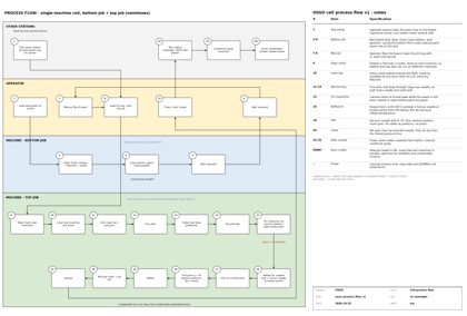
the designer: Parts go on the top side, so the first step is lasing the bottom side of the bare blank, then a manual flip. All remaining operations (top laser, flux, ball drop, tin inspection, reflow, flux, PnP, reflow, clean) run on the top side, so populated parts never rest on the bed. The flip happens before the kit/blank job runs unattended, or as an early pause in the job.
2026-10-22 9:58 AM EDT — Two job types: bottom and top (decision)
the designer: The machine runs two job types. Bottom job: bare blank only, laser the bottom side, then alert the operator. The operator flips the board, loads the parts tray/kit, and starts the top job. Top job: top laser, flux, ball drop, tin inspection, reflow, flux, PnP, reflow, clean, all unattended. The parts tray is only needed for the top job.
2026-10-22 9:59 AM EDT — Bottom and top jobs can run on different machines (decision)
the designer: Bottom and top jobs don't have to run on the same machine. Each machine does its own job alignment check at job start (dowel registration plus a camera fiducial find, and probing where needed), so a board can move between farm machines between jobs.
2026-10-22 10:02 AM EDT — Concept drawings: single-machine cell + process flow (the designer's request)
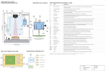
- drawings/osso_cell_concept_v1.py/.png/.pdf: schematic front view of the cell (enclosure, laser-rated window, interlock, fixed galvo + F-theta, 70–110 field, fume extraction, XY gantry carrying the heated bed and dowel-registered carrier plate, folding XYZ head parked outside the field, upward camera, Z probe, shared vac/pressure utility, frame IPA reservoir), head detail (tools A flux, B PnP θ, C ball drop via 23ga Luer + air puff, D IPA + air dry, E hot-air all-metal Luer with heat break; 15–20 clearance), carrier plan, utility schematic, notes table, title block. Overall envelope ~480 W x 420 D x 560 H is a placeholder.
- drawings/osso_process_flow_v1.py/.png/.pdf: swimlane flowchart (other stations / operator / bottom job / top job), steps 1–26 from tray setup to conformal, with per-machine alignment check and farm notes.
- Concept only, no CAD.
2026-10-22 10:59 AM EDT: Cell size TBD; machines as a possible business line
the designer confirmed that the overall size of the single-machine cell is TBD. The ~480 W x 420 D x 560 H mm and ~200 mm carrier figures in osso_cell_concept_v1 are placeholders only. He also noted that OSSO may have a business side in building and selling these machines, alongside the PCB kits.
2026-10-22 11:02 AM EDT: Tool-drop actuation and lock options
Option A (chosen for fast tool changes; to be drawn as a cross section): each folding tool has a tiny single-acting pneumatic cylinder (about 6-10 mm bore) or bellows fed from the shared valve bank, which pushes the tool lever down. A spring detent or over-center toggle locks it against a hard stop (the repeatable tip position, checked by Z touch-off), so it holds if air is lost. A small unlock puff releases the detent, and a return spring folds the tool up. Up is the safe state when nothing is powered. A reed or Hall sensor on each tool confirms which tool is deployed.
Option B (logged as an alternative): no cylinder. The gantry pushes the tool lever against a fixed post at the edge of the bed, like a 3D-printer tool changer, and air is used only for the unlock. It is lighter, but each change takes a few seconds.
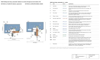
2026-10-22 11:05 AM EDT: Concept drawing: pneumatic tool drop (Option A)
- drawings/osso_tool_drop_pneumatic_v1.py/.png/.pdf: section through one folding tool station, folded up and deployed down/locked side by side. Shows the head body and pivot pin, the tool arm with a Luer-lock blunt needle, a single-acting ~8 mm bore cylinder (piston, rod, link) fed from the shared valve bank, the return spring, a spring ball detent on the hard stop (over-center toggle noted as an alternative), the unlock puff port, a Hall/reed sensor and magnet, and the up stop. Includes section hatching, numbered callouts, a notes table and a title block.
- Fail-safe: the detent holds the tool on the stop if air is lost; the spring keeps it up when unpowered; the cylinder is vented after each move.
- All dimensions are placeholders (~80 W x ~88 H deployed). Concept only, no CAD.
2026-10-22 11:08 AM EDT: Tool drop drawing: part sources
- drawings/osso_tool_drop_pneumatic_v1: added a Source column to the notes table. 3D printed: head body, tool arm, up stop, sensor mount. Off the shelf: 8 mm single-acting mini cylinder (bought for a reliable seal), Luer-lock blunt needle and fitting, spring ball plunger, return spring, Hall/reed sensor and magnet, push-to-connect fittings and tubing, pivot dowel pin. Custom metal: a small stainless or hardened hard-stop/detent insert (item 6, possibly SendCutSend), now drawn as a steel insert. Added the sensor mount as item 14.
2026-10-22 11:12 AM EDT: Cleaning needle is the base tool for the first tool-drop prototype (decision)
the designer: The first tool-drop prototype uses the IPA cleaning needle as its tool. It is the simplest tool (hose-fed, no reservoir, metering or heat). The early risk to test is the IPA and air hoses flexing at the pivot. The PoC is a single tool station cycled on a regulated compressed air feed, built so we can try it.
2026-10-22 11:14 AM EDT: Concept drawing: cleaning-needle tool-drop PoC
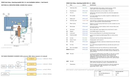
- drawings/osso_tool_drop_clean_poc_v1.py/.png/.pdf: buildable single-station section, deployed and locked. Shows the printed body, the arm with a Luer-lock blunt cleaning needle, IPA (PTFE/FEP) and air hoses with a flex loop beside the pivot to a tee on the Luer hub, the 8 mm single-acting cylinder, return spring, ball plunger in the stainless hard-stop insert, unlock port and Hall sensor.
- Test bench schematic: air source, filter, regulator with gauge (0-60 psi range, set point TBD), manifold, V1 deploy / V2 unlock / V3 puff-dry 3/2 valves (manual or solenoid), V4 IPA from a low-pressure pot.
- The notes table has the Source column and a test plan (cycle count, lock holds with air off, tip repeatability by touch-off, hose flex life). All dimensions and pressures are placeholders.
2026-10-22 1:48 PM EDT – Tool drop mechanical PoC v1 (CadQuery)
- Added cad/tool_drop_mech_poc_v1/. It has no Hall sensor, magnet, manifold or solenoids, and runs on hand-valve air with a dummy needle. Most parts are printed, including the 8 mm printed bore with an O-ring piston.
- Fit check PASS in the deployed and folded states and in a 10° to 80° sweep. Deploy stroke is 10.77 mm.
- BOM.md lists McMaster numbers, with unconfirmed ones marked unverified. Decision: no SendCutSend part. The hardened dowel 91595A122 is the stop wear face, and the ball plunger 3408A93 snaps into a printed notch.
2026-10-22 1:53 PM EDT: Tool-drop PoC build added to TODO
Added the mechanical-only tool-drop PoC build to TODO.md (item 19a). the designer will make his own lower-cost BOM when it is time to build. The McMaster numbers are reference only.
2026-10-22 1:56 PM EDT: Purpose of the mechanical tool-drop test
the designer framed the mechanical-only tool-drop PoC (TODO 19a) as the feasibility test for needle retract: proving that a needle tool can deploy, lock, unlock and fold back up reliably on air alone before anything else is added to the head.
2026-10-22 2:59 PM EDT – Ball dispenser pneumatic index v1 drawing
- Added drawings/osso_ball_dispenser_pneumatic_v1.py/.png/.pdf (approved concept). It uses the v5 stack (BR-G2 carrier and drive, BR-C1 v2 covers, D-spindle), replaces the knob with a printed 24T ratchet on the drive axle, and drives it with an 8 mm printed-bore single-acting cylinder through a spring-return pawl plus an anti-back pawl. The exit is a 23ga Luer blunt needle with a puff port. A manual air schematic (regulator with gauge, PB1 index, PB2 puff) is included.
- Stroke: 15° per pulse at pawl radius R10 gives 2π·10/24 = 2.618 mm; cylinder stroke 3.0 mm to a hard stop (0.4 overtravel).
- Conflicts flagged: (C1) the BR-G2 22T pitch of 16.36° does not divide into 15°, so a separate ratchet is needed; (C2) 12 pockets at 30° with fill to exit 15° means 15° pulses alternate fill and drop, 1 ball per 2 pulses; (C3) the v5 skirt sits below the nozzle tip, so it must be shortened; (C4) the puff can back-flow into the pocket gap, so puff at the fill rest at low pressure; (C5) the 23ga ID of about 0.33 is tight for a 0.25 ball, and the step from the 0.45 chute needs a chamfer; (C6) BR-G2 is FR4, so it is listed as Custom FR4.
2026-10-22 5:17 PM EDT: Pneumatic ball dispenser ratchet decision
the designer chose the 24-tooth printed ratchet for osso_ball_dispenser_pneumatic_v1. Each pulse is 15 degrees (2.62 mm pawl travel, 3.0 mm cylinder stroke to a hard stop). The fill stays aligned with a pocket at rest, and one ball drops every two presses (fill pulse, then exit pulse).
2026-10-22 5:27 PM EDT – Ball dispenser pneumatic index v1 CAD
- Added cad/ball_dispenser_pneumatic_v1/ (CadQuery). It imports the v5 geometry: BR-G2 ×2 and BR-C1 ×2 as REF (already ordered), plus the spindle, hopper, lid and flange. New parts: a printed 24T ratchet on the extended drive-axle D; an 8 mm printed-bore cylinder (3799N21 O-ring) with a stop-sleeve hard stop at 3.0 stroke; a clevis with a torsion-sprung drive pawl; an anti-back pawl; the base with the skirt cut to -12, a 6% Luer taper, a chamfered tip and a puff passage; and a 23ga needle REF with a hub entry cone.
- Fit check PASS: no interference at rest or at the end of the stroke. The drive pawl is 0.02 from the face at the end, giving exactly 15° per stroke (at most +0.125°). The anti-back pawl blocks back-drive with ≤0.31° backlash. Fill and drop alternate on even and odd steps.
- Open issues: the pawl does not stop forward overrun (add a detent if seen); the return stroke over the tooth was not swept; 2 pulses per ball.
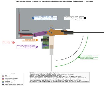
2026-10-22 5:33 PM EDT – Tool-drop mech PoC motion sequence annotation
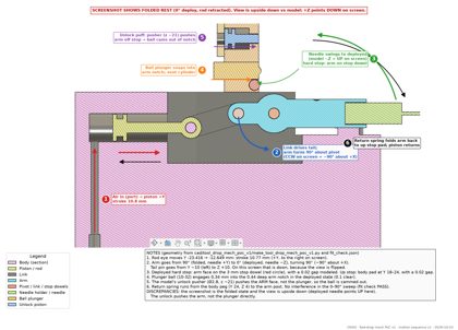
- Annotated the designer's Fusion section screenshot of cad/tool_drop_mech_poc_v1 as drawings/osso_tool_drop_motion_sequence_v1.png/.pdf (script .py), with steps 1–6, a legend and notes. Values are from the model: stroke 10.77 mm and a 90° arm rotation (−90° about +X, folded to deployed).
- Discrepancies: the screenshot shows the FOLDED rest and the view is upside down compared with the model (+Z points down), so the deployed needle swings UP on screen. In the model the unlock pusher (z −21) pushes the arm face and cams the ball out; it does not push the plunger directly.
2026-10-22 5:52 PM EDT – Tool-drop mech PoC v1: linkage past dead center at folded rest (CAD not changed)
- Kinematics from the script. Pivot (0,0). Tail pin at R10 (deployed (0,10); folded (-10,0)). Rod line at z +4, link 14.
- Folded rest: eye (-23.416,4), link angle -16.6°. The moment arm per unit push is +2.86 mm, which turns the arm toward MORE fold, into the up stop. Pushing the rod right jams the arm against the up stop and does not deploy it.
- Dead center is at about 80.4°, so the rest position is 9.6° past center. The rod-eye travel is also non-monotonic (it goes -23.42 → -23.66 → ...).
- Past center the linkage works: at 45° the eye is at -20.73, the link at +12.7° and the arm at -8.45 mm (deploy). At deployed it is -9.04 mm. The arm ends at 0° on the stop dowel and plunger side (-Y face). The return spring torque is positive (fold) at both ends. The unlock pusher (+Y at z -21) gives +21 mm·N, also toward fold. Both are correct.
- Proposed minimal fix, NOT applied: clock the tail pin -20° on the arm (deployed tail (3.42,9.40), folded (-9.40,3.42)). The rest arm becomes -3.03 mm, the motion is monotonic, and the stroke is 13.9. Extend the bore by about 3.1 or lengthen the rod. An alternative is rod_z -4 with an 18 mm link (stroke 16.2).
- The annotation arrows show the intended deploy motion correctly. I did not re-render because the mechanism is at fault.
2026-10-22 6:52 PM EDT – Tool-drop mech PoC v2 (option B) and kinematic checks
- Added cad/tool_drop_mech_poc_v2 (v1 is kept and marked SUPERSEDED in its BOM).
- Rod line z −4, link 18, rod 20, bore y −54…−30.
- The body is lengthened to y −58 with a cylinder belly down to z −10, and the port moves to y −52.8.
- Clearance added: a link groove in the arm (x 2.0–4.6), the tool slot extended to y −31.5, and a rod-eye channel in the stop block.
- Stroke 16.24 mm.
- Added a
kinematics check to fit_check.json (sweep 90→0 at 0.5°).
- The moment arm runs from −2.22 mm (folded rest, the minimum) to −9.93 (45°), always toward deploy.
- The eye moves monotonically (−27.55 → −11.31).
- Dead center is at 98.25°, a margin of 8.25° beyond the rest. The criterion is ≥5° (the up stop prevents going past 90°).
- Interference at rest, deployed and in the sweep is all 0. Hard stop 0.02, up stop 0.02, plunger 0.1. PASS.
- New issue: the return spring center distance goes from 10.2 to 28.4 (×2.79), which no ordinary extension spring covers. I propose a torsion spring on the pivot dowel instead. Not changed yet.
- Updated the preview, BOM and STEP/STL files, regenerated drawings/osso_tool_drop_motion_sequence_v2 from a v2 section render, and pointed TODO 19a at v2.
- Ball dispenser pneumatic v1: added kinematics_check.py and a fit_check
kinematics section. PASS with no geometry change.
- The drive pawl is self-engaging at 30–44° and gives 8.2–10.0 N·mm per N of rod force, after 0.65 mm of free travel.
- The return lifts the pawl up to 10.2° and it drops at 2.7–2.8 of 3.0 (0.25 mm reserve).
- The anti-back pawl is self-engaging at −30°.
- Return spring: 14 free at 0.5 N/mm is recommended.
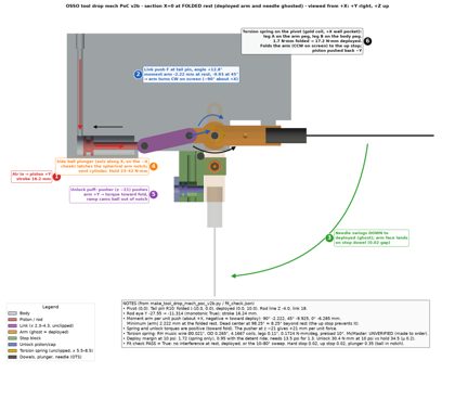
2026-10-22 7:46 PM EDT – Tool-drop v2b: torsion return spring and side detent
- the designer approved replacing the extension return spring. I saved the work as cad/tool_drop_mech_poc_v2b (v2 left as is, with a supersede note in its BOM). TODO 19a now points at v2b.
- Spring (made to order, McMaster number UNVERIFIED): RH music wire Ø0.021", OD 0.265", 4.17 coils, 120° free leg angle, legs 0.11", on a Ø5 arbor boss in a pocket in the +X wall. Leg A bears on a peg in the arm and leg B on a peg in the body.
- k = 0.172 N·mm/deg, 1.7 N·mm folded (10° preload), 9.5 at 45°, 17.2 deployed (100°). Wire stress is 55 % of UTS.
- Removed the extension-spring peg and post. Added the pocket, boss and peg B in the body, and peg A in the arm.
- Torque checks added to fit_check.json (
kinematics.torque, PASS). Friction numbers are estimates.
- Deploy at 10 psi, spring only: 1.72 margin. Return, spring only: 1.35.
- Unlock at 10 psi gives 30.4 N·mm against a hold of 23–35 N·mm (the spring helps). Release margin 1.38.
- Pull-off after the unlock: margin 1.8.
- Found that v2's ball plunger could not latch. Its axis ran along the arm's motion, so the ball only pushed on the arm. v2b uses a side plunger on a new −X cheek of the stop block, with a spherical notch and two 6.5° lead-in ramps. The detent's side load goes through a thrust boss (the arm sits 0.28 mm toward +X).
- The detent ride costs deploy margin near the stop: 0.95 at 10 psi, 1.51 at 15 psi. A 1.3 margin needs 13.5 psi. This is informational, not gating. Printing the plunger backed off 0.1–0.2 mm lowers the ride force.
- The O-ring friction tolerance is small: both 1.3 margins hold only for friction ≤ 0.52 N. Measure it on the first print.
- Interference at rest, deployed and in the sweep is all 0, and the hard stop and up stop gaps are 0.02. I fixed a bad boolean in the arm (the spherical notch after the link groove) and two knock-on overlaps (cheek over the stop dowel hole, Luer needle versus the shifted arm).
- Updated preview.png (now 6 views including the spring plane), BOM.md, the STEP and STL files, and drawings/osso_tool_drop_motion_sequence_v2b (png and pdf). The v2 annotation is kept. Did not sync.
2026-10-23 7:35 AM EDT: Tool drop v2c notes (guide bearings for the pistons)
the designer wants guide bearings for the pistons on the tool drop concept. This is notes only. Do not draw or model until he gives the command.
Plan for v2c, based on v2b:
- Drive piston (8 mm): add a guide bushing at the bore mouth that supports the rod, so the link side load goes into the bushing and not the O-ring seal.
- Unlock piston (6 mm): a short guide bushing around its rod.
- Parts: a flanged sleeve bushing (oil-embedded bronze or a plastic one such as igus) pressed into the body, sized to the rod. The rods become hardened precision pins instead of printed ones. McMaster numbers to be found when modeling.
- Why: v2b has thin friction margins (deploy 0.95 at 10 psi including the detent ride, and return margins hold only while O-ring friction is at or below about 0.5 N). Side load on the O-ring piston from the link is a likely friction source.
- When modeled: re-run interference, sweep, latch and the force/torque checks, and add the bushing friction estimate. Check that the rod eye and link clear the bushing flange.
2026-10-23 7:40 AM EDT: Tool drop v2c direction: single double-acting piston, 30 psi design point
the designer decided to design the tool drop system against 30 psi. Direction for v2c (notes only; no drawing or model until he gives the command):
- One double-acting 8 mm piston with a 4/2 valve (or 5/3 for a center hold): cap side deploys, rod side retracts and releases the latch. Vacuum alone was marginal (about 22 N-mm at the deployed position vs 23-42 N-mm latch release), so pressure is used on both sides.
- The separate unlock piston goes away, which is one fewer printed part. The guide bushing serves one rod.
- At 30 psi the retract/unlock torque is about 65 N-mm, a real margin over the latch release. The rod side has less area because of the rod, so check it explicitly.
- Use a stock McMaster torsion spring (9271K series), stiffer than the made-to-order 17 N-mm one. The spring is the fail-safe that holds the arm up with no air. Check deploy margin at 30 psi and also at lower pressures.
- When modeled, re-run interference, sweep, latch and force/torque checks at 30 psi, with the guide-bushing friction added.
2026-10-23 7:43 AM EDT: Design note: all metric, minimize fastener sizes
the designer set a design rule for OSSO: everything is metric, and the number of different fastener sizes is kept to a minimum. For the tool drop v2c this means M5 instead of 10-32 for the cylinder port threads, with metric push-to-connect fittings and tube (for example 4 mm OD instead of 1/8 inch), and reducing the M2/M3 screws and pins to as few sizes as possible. The earlier 10-32 ball plunger and 1/8 inch tube choices get replaced with metric equivalents when v2c is modeled. Notes only until the designer gives the drawing/model command.
2026-10-23 7:44 AM EDT: Design note: fasteners limited to M5 and M3
the designer wants everything in M5 and M3 only. For the tool drop v2c this means: M5 for the cylinder ports and large threads, M3 for all screws and tapped holes, and no M2 or 10-32. Pins and dowels should be sized to match (3 mm), and the metric ball plunger should use M5 or M3 thread. Notes only until the designer gives the drawing/model command.
2026-10-23 7:44 AM EDT: Design note: exceptions to the M5/M3 rule
the designer allows exceptions to the M5 and M3 only rule. Specialty hardware that is only available in imperial sizes needs his approval before it goes into a design. Specialty hardware in other metric thread sizes (for example M4, M6 or fine-pitch) is fine without asking. Notes only until the designer gives the drawing/model command.
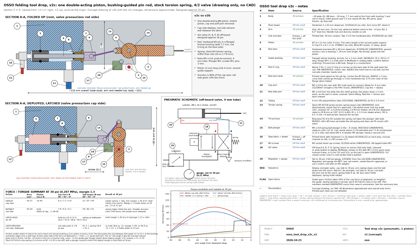
2026-10-23 8:02 AM EDT: Tool drop v2c concept drawing v1 (drawing only)
Made drawings/osso_tool_drop_v2c_v1.py/.png/.pdf (no CAD or model changes; cad/ untouched; no sync). House style: numbered callouts, notes table with a Source column, overall dims only, title block. Shows the section folded and deployed (view from +X), a pneumatic schematic (regulator and gauge at 30 psi, 4/2 valve, cap and rod-side lines, exhaust), the notes table and a force/torque summary. Dimensions approximate; friction values are estimates.
- Forces at 30 psi (0.207 MPa gauge): cap 50.3 mm2 gives 10.40 N; rod side (3 mm rod) 43.2 mm2 gives 8.94 N, 86% of cap, 1.46 N (14%) less.
- Link side load: friction takes about 50% of the cap force at deployed with a 12 mm piston (c = 0.99; c >= 1 would self-lock). Eye force 9.3 / 7.7 / 4.9 N, tail torque 21 / 97 / 49 N-mm at 90 / 45 / 0 deg from deployed. Min deploy margin 1.36 (at 6 deg), 1.3 down to 29 psi, 1.0 at 22.75 psi.
- Retract (rod side): 18 / 82 / 41 N-mm. Replaces the "about 65 N-mm" estimate in the 7:40 AM note; 41 N-mm is the calculated value with side-load friction.
- Spring (calc): RH, 120 deg class, k 0.20 N-mm/deg, 2.0 N-mm folded, 20.0 N-mm deployed. The stock 9271K143-class spring (31.6 N-mm at 90 deg, k 0.35) is too stiff: deploy margin 0.86 even with the plunger scaled to hold it. McMaster's exact 9271K size is UNVERIFIED and inch-dimensioned: needs the designer's approval.
- Latch: hold 26.0 / 31.8 / 38.6 / 46.9 N-mm at mu 0 / 0.1 / 0.2 / 0.3 vs spring 20.0 (margin 1.30, borderline); needs the M5 spring ball plunger scaled to 1.12x v2b (about 2.5 N extended, 7.5 N compressed; availability UNVERIFIED). Release: 41.3 + 20.0 = 61.3 N-mm, margin 1.59 at mu 0.2, 1.31 at mu 0.3.
- Changes from the concept: rod O-ring and wall added (rod-side chamber needs a seal), printed clevis on the pin tip, piston 12 mm long (second guide support), 1.5 mm stand-off and relief groove so the rod-side M5 port is never covered, thrust boss moved outside the spring coil, wall moved back for 0.75 mm flange clearance. A +4 mm guide span would give deploy margin 1.50, release 1.73, c 0.76 (open item).
- Open approvals: inch 9271K spring, NPT/psi regulator and gauge (6763K81), 4/2 valve is open (McMaster shows no 4/2 with M5 and 4 mm ports), any imperial O-ring, the added parts above. UNVERIFIED part numbers are marked in the drawing.
2026-10-23 8:25 AM EDT: Tool drop v2c pressure sweep (calculation only, refs/tool_drop_pressure_sweep_v1.md/.png)
- Calculation only, reusing the v2c calc block unchanged. No drawing, CAD or sync changes. Code in refs/tool_drop_pressure_sweep_v1_code/.
- Spring window (deployed torque, 120 deg class, design margin 1.3 on deploy and release at mu 0.2/0.3, hold sized to 1.30): none at 20 psi (none below 26.9 psi); 30 psi k 0.125-0.200 (13-20 N-mm); 40 psi to 26.8; 50 psi to 34.0; 60 psi to 41.1 (k to 0.435); 80 psi to 55.1. The top edge is release at mu 0.3, about 0.67 N-mm per psi. The v2c drawing spring (20 N-mm) is on the 30 psi top edge; with friction x1.5 there is no 30 psi window.
- Stock 9271K143 (31.6 N-mm, k 0.351, inch, specs verified via listing/mirror) is in the window from about 46 psi, only with a plunger scaled about 1.77x v2b (about 3.9/11.8 N, not found as stock, UNVERIFIED). Stock M5 plungers 10054/10055/10056-SS are too coarse. Metric Samini/MISUMI or Gutekunst 120 deg-class springs are the preferred route (part numbers UNVERIFIED).
- 60 psi: stop-hit energy about 2x (deploy 80 to 158 mJ unthrottled; throttled 22 mJ). Retract hit stays about 50 mJ regardless of throttle, so a soft bumper is needed. Components rated >= 100 psi, 0-100 psi gauge and regulator, compressor >= 80 psi supply. Recommended setpoint 60 psi, floor 50 psi.
2026-10-23 8:29 AM EDT - Tool drop: 60 psi set, plunger elimination
the designer set 60 psi as the target (50 psi floor); compressor innovation later. Imperial springs approved in all cases. He wants the latch plunger eliminated. Options offered: (1) pneumatic hold with cap pressure, fail-safe fold by torsion spring; (2) over-center toggle against hard stop; (3) magnet detent; (4) printed flexure snap. Recommended 2 plus 1; 3 as fallback. Pending his choice; force/torque check on option 2 proposed. No drawing or model work.
2026-10-23 8:30 AM EDT - Tool drop: over-center toggle chosen
the designer agreed on option 2 (over-center toggle against hard stop) as the lock, replacing the plunger. Option 1 (air hold) rejected as too risky. Starting force/torque check on the toggle (calculation only, no drawing or model).
2026-10-23 8:49 AM EDT - Tool drop: over-center toggle check result
Calculation only (refs/tool_drop_toggle_check_v1.md/.png). Verdict: toggle NOT feasible on the v2c geometry at 60 psi. Moment arm negative through the whole sweep (no over-center at deployed position; tail pin would need to move about 64-68 deg). Tolerance stack on past-center angle +-4 deg worst case. Rod-side release margin never above 0.71; hold/release window empty. Fallback: magnet detent, window 47-76 Nmm (aim about 60). Flag: a 2 N tip push at an assumed 40 mm lever (80 Nmm) exceeds that window, so no passive latch can both hold it and release; needs a decision on whether it is a real requirement.
2026-10-23 9:01 AM EDT - Tool drop: digital-control magnet hold
the designer wants a magnet hold with digital control (latching electromagnet: permanent magnet plus coil pulse that cancels the pull). Feasibility can include it, but first tests stay simple: plain permanent magnet detent at about 60 N*mm. Calculation/notes only; no drawing or model.
2026-10-23 9:22 AM EDT - Tool drop: magnet hold sizing (calculation and research, no drawing/model)
refs/tool_drop_magnet_hold_v1.md/.png. Plan A (first tests): two supermagnete S-06-03-N discs (6x3 mm N45), face to face, 12 mm lever, gap about 0.92 mm for about 60 Nmm; hold margin 1.90 vs spring, release 1.94 at 60 psi (1.63 at 1.5x friction); do not run below about 45 psi; M3 screw gap tuning (0.5 mm/turn, about 19 Nmm). Plan B (later, digital): electropermanent holding magnet (Hyab 71-1212-24-JSK first, 71-1811-24-JSK if the tip push must be held) driven by GPIO + MOSFET + flyback; release pulse 0.2-0.3 s after rod pressure. Open: whether a 2 N tip push at 40 mm lever (80 N*mm) is a real load (no passive magnet can hold it and release), lever length, stop block room, 12 vs 24 V, M3 screw access, magnet shop. Pull model needs a gauge check (+-15
2026-10-23 9:27 AM EDT - Tool drop: magnet hold sizing result and Plan B decision
Magnet hold sizing (calculation and research only; refs/tool_drop_magnet_hold_v1.md/.png). Plan A: two supermagnete S-06-03-N discs, 12 mm lever, gap about 0.92 mm for about 60 Nmm; hold 1.90, release 1.94 at 60 psi; not below about 45 psi. Plan B: electropermanent holding magnet, release pulse 0.2-0.3 s via GPIO + MOSFET + flyback. the designer chose Plan B with hold against the 2 N tip push (Hyab 71-1811-24-JSK, 24 V, about 270 Nmm), simple manual test electronics, and commanded the v2d drawing next (drawing only). Open: 40 mm lever, stop block room (3-8 mm deeper), supplier, mount.
2026-10-23 9:45 AM EDT - Tool drop v2d concept drawing delivered (drawing only, not modeled)
drawings/osso_tool_drop_v2d_v1.py/.png/.pdf. Electropermanent latch (Hyab 71-1811-24-JSK) replaces the plunger; folded/deployed sections, latch detail, 60 psi pneumatic schematic, manual test electronics (24 V, pushbutton, flyback diode, optional PTC, later GPIO + MOSFET), force/torque panel (hold 270 N*mm, release capability 116.4, spring 31.6, tip push 80), notes table with Source column and open items. Overall about 115 mm long and 48 mm tall (was 36); stop block about 6 mm deeper. Flags: stop dowel moved to Z -23.5; EPM envelope may interfere with rod/clevis when deployed (CAD check); block needs about 21 mm X by 24 mm Z; armature must stand 1 mm proud; deploy margin needs re-check without the plunger; regulator/valve/fittings rated 100 psi or more; fitting 5225K647 is straight but drawn as elbow. Many part numbers unverified.
2026-10-23 10:42 AM EDT - Tool drop v2d CAD model (cad/tool_drop_mech_poc_v2d)
- Model of the v2d concept drawing, derived from v2b (v2b and v2 untouched): make_tool_drop_mech_poc_v2d.py (CadQuery), 7 printed parts as STL+STEP (body, arm, link, piston, clevis, stop_block, bumper), 23 REF STEPs (dowels, pin rod, bushing, O-rings, 9271K143 spring, Hyab EPM + leads, M3 hardware, M5 fittings, tube, Luer/needle), custom armature plate STEP+DXF, assembly_folded/deployed.step, preview.png (both states, viewed), BOM.md (Source column, McMaster numbers with * unverified, SendCutSend section), fit_check.json (PASS).
- Size: body 22 x 102.75 x 35 mm, block 22 x 12.6 x 25.5, arm 32 mm with a 21 mm paddle. Stroke 16.24 mm.
- Interference sweep (19 states, 5 deg steps, all moving vs fixed): 0 overlaps, smallest non-contact clearance 0.2 mm (link in its arm groove). The drawing's EPM vs rod/clevis overlap is real (clevis 73 mm3, rod pin 16 mm3 at the drawing position), fixed by lowering the EPM 4.5 mm (centre z -16.5, 0.5 mm under the clevis).
- Kinematics: moment arm negative over the sweep (cap push deploys), min |M| 2.22 mm at folded, dead center 8.25 deg beyond folded. 60 psi, 9271K143, no plunger: deploy margin 3.15 / 2.52 / 2.46 at mu 0.2 / 0.3 / 1.5x (1.3 reached at 25.5 / 32 / 33 psi). Rod side + spring give 116 / 100 / 98 N-mm at deployed. EPM hold 270 N-mm (md, 12 mm lever) or 371 scaled to the 16.5 mm lever (UNVERIFIED): vs spring 8.5 / 11.8, vs tip push + spring + shake 2.4 / 3.0. Coil-cancel release (10 percent residual, ASSUMED) margin 4.3 / 3.7 / 3.6 (md), 3.1 / 2.7 / 2.6 (scaled). Pneumatics alone cannot release a latched EPM (0.36-0.43 of hold): pressurize rod side, then pulse the coil. Spring alone only folds the arm to about 65 deg (54 deg at 1.5x) of 90.
- Changes vs the drawing: EPM down 4.5 mm and arm 26 to 32 mm; wide paddle for the Ø18 armature; stop dowel z -23.5 to -28.7 (foot on the block); body 22 wide, belly z -15, top z 20, rear wall 5 mm (M5 thread), 3 mm chamfer; block on two M3 x 30 from the top into heat-set inserts; spring legs trimmed and lost-motion preload (stock 90 deg preload gives 37 N-mm, above the 31.6 rating, because the pegs stiffen the spring to k 0.419); rod O-ring 2.8 ID; armature 1.88 mm so it is orderable from SendCutSend (1008 CRS .074"); stock washers do not work (center hole). Nothing built or measured yet. TODO 19a updated.
2026-10-23 10:42 AM EDT - VERSION v14 snapped
Milestone: the tool-drop needle-retract mechanism has a full CAD model. Frozen to versions/v14_2026-10-23 + OSSO_v14_2026-10-23.tar.gz (the project without versions/, video/, stray root tarballs and ._* files; refs/TOOLS.md copied to the version root). Since v13: tool drop PoC v1 to v2b (torsion spring, plunger), v2c drawing and 60 psi pressure sweep, over-center toggle check (not feasible), magnet hold sizing, v2d concept drawing (electropermanent latch), and the v2d CAD model with BOM and interference/kinematics fit check (cad/tool_drop_mech_poc_v2d); TOOLS.md updated (pyvista, trimesh, BRepExtrema, sweep technique, SendCutSend plate). The docs site now lists v14. Mac sync excludes versions/ and video/ as before.