New in this snapshot: 38 drawings, 0 STEP files, 3 documents/media.
Oct 15, 2026, 12:15 PM ET: Concept G (v2)
- Wiring slot kept at 27x12 (concept F); window 27x74; 35 dual-orientation sites.
- Added two 7x5 plated 2.54mm through-hole zones near the right edge, above and below the wiring slot, for wire-to-board connectors, headers, and strain relief. These carry no stack signals (they sit over the window below when flipped). Drawing: drawings/osso_base_v2g.png
- 12:15 PM ET: Variant G2 shrinks each TH zone to 6x4 (about 13x8mm), still near the edge with about 5mm clearance to the slot. Drawing: drawings/osso_base_v2g2.png
Oct 15, 2026, 12:20 PM ET: Concept H (v2), board grown to 140x140mm
- the designer wanted more room for SMT parts. Board is 140x140; 10mm grid now runs 10–130.
- Window (27x74), wiring slot (27x12), and the 6x4 TH zones are unchanged in size and stay at the edges, centered vertically.
- 123 interposer sites work in both orientations (up from 35). Note: 140mm is still under the laser's 150x150 field, but with very little margin. Drawing: drawings/osso_base_v2h.png
- 12:21 PM ET: Concept H2 halves the sites to 61 using a checkerboard (every other 10mm site). Still flip-symmetric, and each pad has about 14mm of diagonal spacing for SMT parts. the designer's intuition: 123 was more than needed. Drawing: drawings/osso_base_v2h2.png
- 12:23 PM ET: Concept J collects the sites into a compact center block: 4 columns at 7.62mm and 15 rows at 5.08mm, for 60 sites, about 31x77mm under one 3D-printed interposer. It is flip-symmetric about the board center. Gaps are about 3.6mm side to side and about 3.1mm top to bottom, which is room for traces but not parts. Everything else is open for SMT. Drawing: drawings/osso_base_v2j.png
- 12:25 PM ET: Concept J2 adds 12 M2 anchor drills (2.2mm clearance holes) for the printed interposer: 5 along each long side at 15.24mm pitch (x = center ±18) and 1 at each end. The pattern is flip-symmetric, and the interposer footprint is now about 42x88mm. Drawing: drawings/osso_base_v2j2.png
- 12:27 PM ET: Concept J3 adds a ring of M2 frame anchors around the board edge at the same 15.24mm pitch, centered and inset 3.5mm. The ones next to the corner M3 holes are dropped, and the edges beside the window and slot are skipped (they are too close to the companion pads and openings). That leaves 18 frame anchors plus 12 at the center block, all flip-symmetric. Drawing: drawings/osso_base_v2j3.png
- 12:28 PM ET: Concept J4 sets all M2 anchors to 20mm pitch: 22 around the frame (centered at 10–130mm, inset 3.5mm, skipped beside the window and slot) plus 10 at the center block (4 per side at ±10 and ±30mm, plus 1 at each end). All are flip-symmetric. Drawing: drawings/osso_base_v2j4.png
- 12:29 PM ET: the designer dropped the frame anchors next to the corner M3 holes. The frame now has 14 M2 anchors at 20mm pitch (30–110mm), plus the 10 at the center block. Drawing updated: drawings/osso_base_v2j4.png
Oct 15, 2026, 12:32 PM ET: Concept K (v2), routing fixes
- Pogo columns moved to 10.16mm pitch (about 8mm escape channels); rows stay at 5.08mm.
- Companion vias changed to via-in-pad (0.6mm, filled and capped) so pads AND vias match exactly when flipped 180 degrees. Any offset via, beside or above, mirrors when flipped, so via-in-pad is the clean fix.
- Window moved 3mm inward (x=10) for an edge routing lane, and the slot moved to x=103 to stay mirrored over the window. The edge M2 anchors there are now allowed (20 frame plus 10 block). The interposer footprint is about 48x88mm.
- Drawing: drawings/osso_base_v2k.png
- 12:33 PM ET: Concept K2 drops all 10 inner M2 anchors. the designer reasons that board rigidity prevents flex, and the space adds routing freedom. The interposer is held by the 20 perimeter frame anchors only, and the block footprint is about 37x77mm. Drawing: drawings/osso_base_v2k2.png
- 12:35 PM ET: Concept L. the designer noted that a via in the pad is wrong, because the upper and lower pogo pads can be different circuits. Pads are now isolated top and bottom. Layer-change vias are a separate system: a row of 23 vias (0.6/1.0mm at 5.08mm pitch) runs just inside the top and the bottom frame anchors (y=7.5 and 132.5), 46 total, flip-symmetric. Drawing: drawings/osso_base_v2l.png
- 12:38 PM ET: Central via layout options drawn (red). A: 42 vias in the channels between pogo columns, offset half a row. B: 38 vias in a ring hugging the pogo block. C: 58 vias on a sparse 10.16mm grid over the open SMT areas. All are flip-symmetric. Files: drawings/osso_base_v2l_{a,b,c}.png and osso_base_v2l_options.png
- 12:39 PM ET: the designer chose via Option A (vias in the pogo channels), provided traces that skip a via can route around it. Check: each channel has about 8.2mm clear, a 1.0mm via pad leaves about 3.5mm per side, and the half-row offset keeps the paths between pads clear.
Oct 15, 2026, 12:42 PM ET: Concept M (v2), companion boards
- The wire route is the slot of the board above, flipped 180 degrees. It lands as a 27x12mm band across the full window width (y about 64–76).
- Upper and lower companion boards are each about 34x27mm. They bridge the window and lap-solder to SMT pads on both edges, with about 2mm clearance to the wire route.
- SMT lap pads now sit only under the companions, 40 total (10 per edge per board). Pads beside the wire route were removed.
- Channel vias (Option A) are included. Drawing: drawings/osso_base_v2m.png
- 12:45 PM ET: Interposer overlay drawn. It has a continuous 6mm printed ring around the edge (0.5–6.5mm in from the edge, covering the M2 and M3 holes) and 4 pin columns, each 4.6mm wide and about 77mm tall, over the pogo columns. The channel vias between the columns stay uncovered. Open issue: the columns float, so they need ties to the ring or a top layer to make one printed part. Drawing: drawings/osso_base_v2m_interposer.png
- 12:47 PM ET: Correction from the designer. The 4 pin columns run full height into the top and bottom of the ring, so the interposer is one printed part. Side effects: the columns now divide the board into a left area (window and companions), three narrow channels, and a right area (slot and TH zones), and they cover 8 of the edge-row vias where they cross. Traces between the left and right sides must pass under the columns on the bottom layer or through the channels. Drawing updated: drawings/osso_base_v2m_interposer.png
- 12:49 PM ET: Interposer revised. The 4 pin columns are joined by crossbars above and below the pin block, and a single 4.6mm center spine runs from each crossbar to the ring. The interposer is one part again, with much more open board. The channels between the columns are now enclosed on the top layer, so the channel vias are the exit to the bottom layer. The spine covers 1 via in each edge row. Drawing updated: drawings/osso_base_v2m_interposer.png
Oct 15, 2026, 12:51 PM ET: Concept N (v2)
- Pogo block cut to 10 rows: 4 columns x 10 rows = 40 sites, block about 36x52mm, centered and flip-symmetric. Channel vias are now 27.
- The interposer (ring, crossbars, and center spine) is unchanged in form, and the spines are longer. Drawing: drawings/osso_base_v2n.png
Oct 15, 2026, 12:55 PM ET: Concept P (v2)
- the designer clarified: traces CAN run under the 3D print; only tall components are blocked. Idea to keep: build a 2–3mm raised "bridge" into the print so low-profile parts can sit under it.
- (4) Side via columns: 13 vias at 5.08mm pitch at x=48 (between window and block) and x=92 (between block and slot), flip-symmetric.
- (5) Companion anchors: each companion widened to about 39mm with 2 M2 holes into the base, beside the window, to take strain off the solder laps.
- (6) Note: the corner M3 standoffs pass through the ring, and their length must match the pin stack height.
- (7) Laser fiducials at 3 corners (asymmetric set) plus a pin-1 / orientation triangle at top left.
- Drawing: drawings/osso_base_v2p.png
Oct 15, 2026, 1:00 PM ET: Concept Q (v2), drawing cleanup
- Side via columns from P removed (the designer: not needed, does not like them).
- Drawing rebuilt cleanly: all notes moved into 16 numbered callouts with a notes table (item and specification) and a legend. Only overall 140mm dimensions stay on the board view. The edge-row vias under the center spine are dropped.
- Script: drawings/base_v2q.py. Drawing: drawings/osso_base_v2q.png
- 1:01 PM ET: Rationale (the designer): the center interposer keeps the outer edges free for user-facing parts like LEDs, switches, and sensors, which are reachable from outside the stack.
Oct 15, 2026, 2:28 PM ET: Concept R (v2), power corners
- the designer looked at Kyocera AVX 9296 Poke-Home single contacts (18 AWG, up to 15A UL) for a threaded bus wire, then proposed brass bushings in the corners instead. Decision: the corner M3 positions become the high-current bus. Brass standoffs clamp the stack and carry current.
- Polarity: + at top-left and bottom-right, − at top-right and bottom-left (diagonal pairs), so it is preserved under the 180 degree flip. One high-amp bus only; the designer doubts multiple high-amp buses are needed.
- Each corner has a 7mm ENIG ring pad with 9mm laser isolation. The printed ring needs corner clearance so the standoffs contact the boards. Washers (star or wide) give a good contact.
- Pin-1 mark nudged inward. Drawing: drawings/osso_base_v2r.png
- 2:30 PM ET: Correction from the designer. The board flip is left-to-right, so + goes on both top corners and − on both bottom corners (not diagonal). Drawing updated: drawings/osso_base_v2r.png
- 2:33 PM ET: Bus rating. Rough estimate is about 10A per corner, about 20A per rail with two corners in parallel (contact pressure and 1oz copper are the limits). the designer chose to derate: 10A per rail (480W at 48V). Bench test to add: 2 boards plus standoffs, loaded at 10A and 20A, measure corner temperature.
- 2:44 PM ET: To-do (the designer): a safety over-enclosure for the stack, since the exposed brass bus standoffs carry up to 10A / 480W. Possibly an evolution of the 3D-printed edge trims.
Oct 15, 2026 2:45 PM ET: Power feed via ring terminal
the designer: feed the corner power bus with a ring terminal on the top screw fastener of each corner. It is a simple, standard connection. Note: the top joint carries the full rail current, so use a star washer and torque it properly.
Oct 16, 2026 9:45 AM ET: Concept S (v2), taller slot, stretched companions, no frame anchors
- Wiring slot is now 27x26mm at (103,57), up from 27x12. Same width and x, still vertically centered on y=70. The matching wire-route keep-out in the window is now (10,57,27,26), so the slot and window stay mirror-aligned under the left-to-right flip.
- Companion boards now run from 2mm off the wire route to the outer (top/bottom) end of the window. Lower companion: y 33–55. Upper: y 85–107. Both are x 6.6–45.5, about 39x22mm. Lap pads: 8 per soldered side, 16 per companion, 32 total (was 40), 2.0x1.0mm @ 2.54mm. The 4 M2 companion anchors are kept.
- All 20 perimeter M2 frame anchor drills removed. The corner M3 power standoffs are kept. Callouts renumbered 1–15 (old 14–16 become 13–15).
- TH zones moved out of the taller slot's path. They are now at y0=87 (upper) and y0=45.38 (lower), symmetric about center, with 2mm clearance to the slot.
- Script: drawings/base_v2s.py. Drawing: drawings/osso_base_v2s.png
Oct 16, 2026 9:50 AM ET: Concept T (v2), narrow vertical slot, rotated TH zones
- Wiring slot narrowed to 12x26mm (vertical) at (118,57), centered on y=70. Its right edge stays at x=130, 10mm from the board edge. ("Window" in the designer's request read as the wire slot; the 27x74 window is unchanged.)
- Wire-route keep-out narrowed to match: (10,57,12,26), on the left side of the window, mirror-aligned under the left-to-right flip.
- Companions and pads unchanged: ~39x22mm at y 33–55 and 85–107, 8 pads per side, 32 total. The keep-out height is unchanged, so the 2mm clearance holds.
- TH zones rotated 90° to 4 wide x 6 tall @ 2.54mm. Hole columns x 120.38–128, in line with the slot. Upper holes y 87–99.7, lower holes y 40.3–53. Each keep-out box clears the slot by about 2.6mm.
- Script: drawings/base_v2t.py. Drawing: drawings/osso_base_v2t.png
Oct 16, 2026 9:50 AM ET: Concept T note
the designer: leave the strip freed by the narrower wire route (x 22-37, y 57-83) open for SMT. No extra companion pads and no merged companion.
Oct 16, 2026 9:52 AM ET: Concept U (v2), companions to the board edge, interposer skyline
- The left edge of both companions moves out to the board edge, x=0. Right edges, heights and pads stay as they were. Companions are now 45.5x22mm: lower at (0,33)–(45.5,55), upper at (0,85)–(45.5,107). Still 32 lap pads, 8 per side.
- The companions overlap the interposer ring on purpose. the designer: the 3D print gets "skylined" (cut away) at x 0.5–6.5 over each companion, so the companion and any edge-mounted parts show through. This is new callout 16.
- The strip between the companions (x 22–37, y 57–83) stays open for SMT.
- Script: drawings/base_v2u.py. Drawing: drawings/osso_base_v2u.png
Oct 16, 2026 10:05 AM ET: Interposer height locked
Interposer gap locked at 11.5mm (stack pitch 13.1mm with 1.6mm boards). TH zones clear through the window of the flipped board above when no companion is mounted there. Pin requirement: double-ended, collared, >=1A. Pin choice still TBD; several stocked non-custom options exist at this height (Xinyangze YZD0029-20135-01, YZD0047-25131-01, generic 13mm collared pins). See refs/pogo_selection.md.
Oct 16, 2026 10:10 AM ET: Concept U (v2), stack side view, 10 boards
- New left-side view of the stack (looking at the x=0 edge; horizontal axis is board y 0–140, drawn increasing left to right).
- 10 boards, 1.6mm FR4, 11.5mm gap, 13.1mm pitch: 9x13.1+1.6 = 119.5mm, hardware excluded. Total height, pitch, board thickness and gap are dimensioned.
- B1 (bottom) is unflipped. Even boards (B2..B10) are flipped left-to-right. Assumption: companions are lap-soldered on TOP of the unflipped boards (B1, B3, B5, B7, B9) and sit in the gap above. Flipped boards show the slot/TH side, with no companions.
- Interposer ring hatched in every gap, with skyline cutouts at y 33–55 and 85–107 above the unflipped boards. Pogo columns are shown dashed (hidden). Brass standoffs at y=5 (−) and y=135 (+) run the full height, with a ring terminal, star washer and nut on top and a nut at the bottom.
- Script: drawings/base_v2u_side.py. Drawing: drawings/osso_stack_side_v2u.png
Oct 16, 2026 10:11 AM ET: Enclosure envelope
the designer: the safety over-enclosure target is a 150x150x150mm cube. That leaves about 5mm per side around the 140mm boards and about 30mm of headroom above the 10-board, 119.5mm stack for top-board components, standoff hardware, ring terminals and walls.
Oct 16, 2026 10:12 AM ET: Stack vs multilayer
the designer: a 10-board stack is roughly equivalent to a 20-layer PCB built from economical 2-layer boards. Some signal paths are longer, but total SMT area is much larger. Caveat (OSSO): board-to-board interconnect is limited to the 40 pogo sites per gap, versus vias anywhere on a true multilayer, so it suits modular, bus-style designs.
Oct 16, 2026 10:13 AM ET: Partitioning
the designer: deciding what goes on each board takes extra routing intelligence, but it may need fewer vias, since signals that must be close stay on one board. Idea: a future OSSO software tool that suggests how to split a design across the stack.
Oct 16, 2026 10:14 AM ET: Spec drives partitioning
the designer: the Spec (here, the schematic) drives the decision of what goes on which board. This ties directly to "Open Source Spec to Object": schematic in, board partitioning, laser-ready boards out.
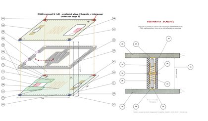
Oct 16, 2026 10:16 AM ET: Concept U (v2), exploded view
- New oblique exploded view: B1 (unflipped, with companions on top), the interposer (ring, 4 pin columns, crossbars, center spine, skyline cutouts, corner clearances), and B2 (flipped left-to-right, no companions). Pogo pins are dashed between the boards. The brass corner standoffs are dashed through all layers, with ring terminals on the + top corners.
- All 16 plan-view callouts plus the side-view items are merged into one table of 23 callouts.
- Simplifications: the vertical explode and the slab thicknesses are not to scale (gap and pitch are given as dimensions). There is no hidden-line removal on the lower board under the interposer. The edge-via circles are simplified.
- Script: drawings/osso_exploded_v2u.py. Drawing: drawings/osso_exploded_v2u.png
Oct 16, 2026 10:20 AM ET: Concept U (v2), exploded view with section A-A (2 pages)
- Page 1 is the exploded view with callout bubbles only, plus the A-A cut through one pogo site in pin column 1. Next to it is a SECTION A-A at 6:1 (relative to the 18x10.5 in sheet). Page 2 has the full notes table (callouts 1–35) and the legend.
- The section shows: B1 and B2 (1.6mm) with their Ø2.0 ENIG pads, the 11.5mm working gap, and the printed column (~4.0mm) in section hatch. The column has a Ø2.1 bore and a collar pocket, and a two-piece print split line at the pocket mid-plane. Also shown: the Ø2.0 barrel with its collar, ~Ø1.2 plungers compressed onto the pads, and the internal spring.
- Pin: Xinyangze YZD0029-20135-01, marked TBD, representative (13.5 free / 11.5 working / 2.0 travel / Ø2.0). Assumed, not from the datasheet: bore Ø2.1, pocket Ø2.8x0.9, collar Ø2.5x0.6, barrel length 7.5, plungers Ø1.2 with ~1mm compression each, column walls ~0.95mm.
- Script: drawings/osso_exploded_v2v.py. Outputs: drawings/osso_exploded_v2v_p1.png, drawings/osso_exploded_v2v_p2.png, drawings/osso_exploded_v2v.pdf
Oct 16, 2026 10:22 AM ET: VERSION 2 FROZEN
the designer snapped the current state as Version 2. Snapshot: versions/v2_2026-10-16 (drawings, refs, journal). Key files: base_v2u (plan, concept U), osso_stack_side_v2u (side), osso_exploded_v2v (exploded view plus section A-A, 2 pages). Locked: 140mm board, 11.5mm interposer gap (13.1mm pitch), corner brass power bus at 10A per rail, 32 companion pads, 150mm cube enclosure. Pin TBD. Everything after this is v3.