New in this snapshot: 1 drawings, 6 STEP files, 5 documents/media.
Oct 16, 2026 3:17 PM ET: Jig v4b Bambu Studio 3MF projects
- Added cad/jig_v4b/jig_v4b_base.3mf and jig_v4b_carrier.3mf, plus the generator make_3mf.py. Each has one plate with the part flat and centered. Saved through the Bambu Studio 02.08.02.61 CLI (AppImage on the box, headless).
- Presets: Bambu Lab P1S 0.6 nozzle / 0.30mm Standard @BBL X1C 0.6 nozzle (no P1S-named 0.6 process exists) / Bambu PETG HF @BBL X1C 0.8 nozzle (the system HF profile whose compatible list includes the P1S 0.6; 245 °C). Textured PEI.
- Settings: 0.30 layers, 0.62 lines, 5 walls, 40% gyroid, 6 top / 5 bottom, no supports. 100% infill modifiers: base 19 (M6 cb floors, M4 inserts, posts); carrier 9 (dowel bosses, clamp inserts, pull inserts).
- Validated: both files reload and slice in the CLI with no errors. Gcode settings match. Estimates: base 8 h 22 m / 487 g, carrier 3 h 47 m / 216 g.
- Open: the designer to confirm the presets load in his Studio version and the plate type.
2026-10-16 3:31 PM ET — Jig material path
- First jig prints in black PETG HF (HF 0.6 nozzle, Cool Plate SuperTack) for mechanical/fit tests. Note: black PETG marks easily under laser; clip jobs to board, cover margins.
- Plan: once dialed in, the designer may have an aluminum CNC jig made. OSSO to convert the parametric CAD to a machinable design (reamed dowel bores, tapped holes instead of heat-set inserts).
2026-10-16 10:08 PM ET — Carrier v4b print feedback
- First carrier print (face-down): dowel pin holes collapsed without supports.
- Decision: print carrier support-face UP next revision; the designer judges PCB flatness matters more than print-face flatness (OSSO agrees: PETG top surface well within galvo focal depth; watch warp/pillowing).
- Decision: remove all relief pockets (cutouts are factory-routed, ENIG pads fine on plastic); full flat support face.
- More refinements from the designer pending before regenerating.
Oct 16, 2026 10:14 PM ET: Jig v4c carrier (face-up, no pockets)
the designer's first carrier print (v4b, support face down): the dowel holes collapsed without supports, and the first layers were messy while the top layers were perfect.
- New folder cad/jig_v4c/. Files:
- jig_v4c.py (from v4b), jig_v4c.step (base + carrier + ghost board)
- jig_v4c_base.stl (unchanged geometry), jig_v4c_carrier.stl
- jig_v4c_base.3mf, jig_v4c_carrier.3mf, make_3mf.py
- verify.py, render.py, preview_carrier_faceup_iso.png, preview_carrier_edge_iso.png
- PRINT_NOTES.md
- Carrier changes:
- All relief pockets removed (window, slot, TH zones, corner rings, fiducials). The support face is fully flat; the cutouts are factory-routed and ENIG sits fine on plastic.
- Prints support face UP, with the base-mating face on the bed. The dowel holes (still Ø2.8 x 10 / Ø1.8 x 9 undersize, to ream) are open-topped blind holes.
- The pull-insert (Ø4.0) and push-pad (Ø7x1) horizontal edge holes are now truncated 45° teardrops, so they need no support.
- Everything else is vertical or through: M4 slots, M6 U-notches, clamp inserts.
- The 0.6 mm chamfers stay on the outer perimeters only.
- 3MF presets:
- Printer: P1S 0.6 nozzle with nozzle flow = High Flow (no separate P1S HF printer preset exists; it's the HF variant of the P1S 0.6, max volumetric 29 mm³/s).
- Process: 0.30mm Standard @BBL X1C 0.6 nozzle.
- Filament: Bambu PETG HF @BBL X1C 0.8 nozzle, black.
- Plate: Cool Plate SuperTack, 70 °C.
- Modifiers kept: base 19, carrier 9.
- Validated:
- STEP reimports as 3 valid solids; both STLs watertight.
- Probe points check the flat face, open dowel tops and teardrops.
- Both 3MFs reload and slice headless in BS 02.08.02.61. Estimates: carrier 3 h 23 m / 217 g, base 7 h 46 m / 488 g.
- Notes: let the part cool fully on the plate before removal; check flatness with a straightedge. Black PETG absorbs UV, so keep it out of the beam.
- Open: the designer to confirm High Flow shows in his Studio nozzle settings and the presets load.
2026-10-16 10:35 PM ET — 3MF fix (v4c)
- jig_v4c 3MFs failed in the designer's Bambu Studio 02.08.02.60 ("Invalid configuration file", no geometry). Cause: High Flow nozzle setting expanded per-variant arrays (Standard + High Flow) in project_settings.config.
- Fix: jig_v4c_carrier_safe.3mf / jig_v4c_base_safe.3mf use the v4b settings block (known good) with only plate=SuperTack and color=black changed; the designer sets Nozzle flow = High Flow in Studio. Confirmed opening on his Mac.
- Lesson: for 3MFs, do not bake High Flow variant arrays; let user toggle nozzle flow.
2026-10-17 9:12 AM ET — Carrier v4c print result
- v4c carrier printed perfectly face-up; earlier bottom defects resolved (likely floating cantilevers ripping layers, not nozzle). SuperTack bottom is perfectly smooth.
- Decision: v4d flips carrier back to face-down (board face on bed) with teardrops flipped; nozzle left Standard in 3MF (the designer sets HF).
Oct 17, 2026 9:16 AM ET: Jig v4d carrier (board face down again)
- Folder cad/jig_v4d/. Files:
- jig_v4d.py (from v4c), jig_v4d.step (base + carrier + ghost board; base unchanged)
- jig_v4d_carrier.stl (print orientation, board face on bed)
- jig_v4d_carrier.3mf, make_3mf.py
- verify.py, render.py, preview_carrier_print_orientation.png
- PRINT_NOTES.md
- Geometry vs v4c:
- Carrier prints with the board-support face down on SuperTack.
- Dowel and clamp-insert holes are blind holes open at the bed face. Their ends are now 90° cones (truncated at Ø0.6), so the ceilings build themselves.
- Ø2.8 dowel depth went 10 → 9.5 to keep 1.1 mm of skin under the cone. Ø1.8 stays at 9.0; the reaming plan is unchanged.
- Edge teardrops are mirrored (point at −Z in part coordinates = up as printed).
- Chamfer is 0.5 mm on the board-face perimeter only, clear of the dowels. No chamfer on the base-mating face.
- M4 slots and M6 notches go straight through. No supports.
- 3MF:
- project_settings.config is byte-identical to jig_v4c_carrier_safe.3mf (nozzle Standard, Supertack, black, v4b settings).
- Only the geometry and model_settings differ. The 9 modifiers at 100% infill are repositioned.
- the designer sets Nozzle flow = High Flow himself.
- Validated:
- STEP reimports as 3 valid solids; STL watertight.
- 17 probe points pass.
- BS CLI --info: manifold = yes, 160x160x12.
- Slice: 3 h 42 m / 217 g at Standard flow.
2026-10-17 9:36 AM ET — v4d print + flatness reference
- v4d carrier (face-down) printing; first layer clean, no issues.
- the designer has a professionally ground surface plate available as a flatness reference; carrier faces can be lapped (sandpaper on plate, figure-eight) if needed.
Oct 18, 2026 3:41 PM ET: Jig v4e (modifier clearances, deeper inserts, two carrier orientations)
- Folder cad/jig_v4e/. Files:
- jig_v4e.py, jig_v4e.step (base + carrier_facedown + ghost board), jig_v4e_carrier_faceup.step
- STLs: base, carrier_facedown, carrier_faceup
- 3MFs: jig_v4e_base.3mf, jig_v4e_carrier_facedown.3mf, jig_v4e_carrier_faceup.3mf
- make_3mf.py, verify.py, PRINT_NOTES.md
- Modifiers: the 100% modifiers spanned the full height and left visible artifacts on the top and bottom skins. They're now pulled back: start ≥ 1.8 above the bed face, end ≥ 2.1 below the top, inset 3.2 behind the outer walls.
- Base: M6 floors z 1.8–3.9; M4 z 6.0–15.9; post cores z 16.5–27.9.
- Carrier: z 1.8–9.9. Clamp modifiers shrank Ø10 → Ø7.6 to stay behind the wall.
- Heat-set inserts weren't seating flush. All bores are +0.5 mm: M3 7.0 (carrier clamps x4, carrier pulls x3, base post pushes x3), M4 10.5 (base x4). Thinnest remaining wall is 3.3 mm (the clamp floor beyond the cone); nothing went under 1.0.
- Carrier orientations: face-down (v4d style) and face-up (v4c style, teardrops mirrored to point up as printed). the designer picks after comparing.
- 3MF: project_settings.config is byte-identical to jig_v4c_carrier_safe.3mf in all three (nozzle Standard, Supertack, black); the designer sets High Flow.
- Validated:
- STEPs reimport as valid solids; STLs watertight; 33 probe points pass.
- BS CLI --info: manifold for all three. Slices clean.
- Estimates: base 8 h 17 m / 486 g, carrier face-down 3 h 42 m / 217 g, carrier face-up 3 h 41 m / 217 g.
2026-10-18 3:57 PM ET — Heat-set insert fit (Ruthex)
- the designer uses Ruthex RX inserts (has both standard and short). Insert pilot end would not start in printed holes drawn at Ruthex nominal (M3 Ø4.0, M4 Ø5.6); printed holes run ~0.1-0.2mm undersize.
- Pending for next jig version: insert holes +0.2mm (M3 Ø4.2, M4 Ø5.8); depths already exceed L+1mm (standard M3 5.7, M4 8.1). Workaround on current parts: hand-drill to 4.2/5.8.
- Reprint on hold until the designer provides laser alignment (galvo center vs grid, focal height); fold offsets in then.
Oct 18, 2026 7:07 PM ET: OSSO blank v3b STEP model
- Folder cad/blank_v3b/. Files:
- OSSO_blank_v3b.step: FR4 substrate, 140x140x1.6, board frame z 0–1.6, plus ENIG_top and ENIG_bottom pad bodies 0.035 thick.
- make_blank_v3b.py: parses the GKO and the Excellon PTH/NPTH files; no coordinates retyped.
- jig_v4e_with_blank_v3b.step: drop-in check, board at z 30–31.6 on the face-down carrier.
- Also: OSSO_blank_v3b_substrate.stl, OSSO_blank_v3b_preview_iso.png, verify_holes.py, verify_holes_output.txt, HOLE_COUNTS.md.
- Holes match the drill files exactly by diameter and XY: PTH Ø0.3 x71, Ø0.4 x2, Ø1.0 x48, Ø3.2 x4; NPTH Ø2.2 x4, Ø3.0 x1, plus one Ø2.0 G85 slot. Cutouts: window 27x74 R5, wiring slot 12x26 R4. Substrate valid; volume matches the analytic value.
- ENIG: 40 pogo Ø3 per side, 4 corner rings Ø7/Ø3.2 per side, fiducial rings and lands, 32 top lap pads. 132 bodies.
- Finding: the NPTH slot in the ordered drill file is X70Y135 G85 X70Y137 with a Ø2.0 tool. That makes a 2.0 x 4.0 obround (y 134–138), not the 2.0 x 3.0 in FAB_NOTES and base_v3b. The copper clearance in the Gerbers was drawn for 3.0 (centers 135.5/136.5), so a 4.0 route would nick about 0.2 mm of copper pour at each end, under the mask. The Ø2 slot dowel still works; it just gets 2 mm of free travel along y instead of 1. Measure the real boards when they arrive. For future fabs, fix gen_v3b_gerbers.py to centers (70,135.5)-(70,136.5).
2026-10-19 9:01 AM ET — Interposer gap changed to 12.0mm
- the designer can source hex standoffs at 11mm and 12mm (not 11.5). Decision: 12mm standoffs; interposer gap locked at 12.0mm (was 11.5mm).
- Stack pitch 13.6mm; 10-board stack = 10x1.6 + 9x12 = 124.0mm (was 119.5). Fits 150mm cube.
- YZD0029-20135-01 (13.5 free / 11.5 rated working) compresses 1.5mm at 12mm gap: slightly lighter contact force, no bottoming. 11mm rejected (0.5mm past rated working height).
- Follow-ups: update side view, exploded views, interposer model, pogo_selection.md to 12mm gap.
2026-10-19 9:06 AM ET — Corner standoff confirmed
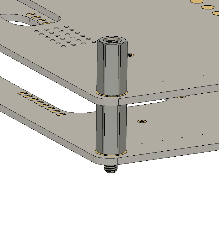
- the designer modeled a standard 12mm M3 male-female hex standoff between two boards on the corner ring pads (refs/designer_standoff_12mm_cad_2026-10-19.png). Looks good; adopted as the corner power-bus fastener (brass, 12mm body).
2026-10-19 9:24 AM ET — Component height limit in interposer zones
- DECISION: max component height in the interposer gap zones is 10mm (case dia up to ~10mm), leaving ~2mm clearance under the 12.0mm gap for solder, flex, and the underside of the board above.
- Context: Nichicon PCL0E222MCL1GS (2200µF/2.5V, 8×12, 12.5mm seated) does not fit under solid board; OK under the window, through-hole zone region, or the top board.
- At 10mm, polymer caps top out around 2700µF@2.5V, 2200µF@4V, 820µF@10V, 470µF@16V (PCL 10×10). Taller parts (8×12, 10×12.7, ≥12.5mm hybrids/electrolytics, supercaps, mains film) go on the top board, under the window, or get split into parallel smaller caps.
2026-10-19 10:04 AM ET — Current limits and board-to-board power
- DECISION: 5A max per internal rail on an OSSO board.
- DECISION: each pogo connection carries no more than 1A (its rating). No paralleling pogo pins to carry more current: if some pins fail, the survivors exceed spec.
- DECISION: board-to-board power above 1A goes through a wiring harness (e.g. via the 12×26 wiring slot), not the interposer.
- Consequence: wound parts are a non-issue at ≤5A. Shielded power inductors 2.2–22µH are ~5×5 to 8×8mm and ~3–8mm tall, inside the 10mm height rule. Details in refs/inductors_10mm.md.
- the designer: "we have to start accepting constraints."
- 10:06 AM ET addendum: board-to-board harness connections use Kyocera AVX wire-to-board connectors (poke-home or IDC), harness rated up to 5A max. Heights/ratings to be checked against the 10mm rule.
- 10:06 AM ET addendum: harness wires are terminated once at manufacturing time (IDC or poke-home), not field-reworked, so the 9176 IDC's 3-cycle re-termination limit is a non-issue. Candidates: 9296-400 poke-home (SMT, 3mm tall, 4mm pitch, 1–6p, 8A UL / 6A cUL at 22AWG) and 9176-000 IDC (18–24AWG, 10A/contact; height TBD).