New in this snapshot: 3 drawings, 1 STEP files, 7 documents/media.
Oct 16, 2026 11:36 AM ET: ENIG gold thickness
Test board: 1u" immersion gold (PCBWay default). Later revisions: consider upgrading to 2u" for wear on the repeatedly mated pogo and corner contact pads.
Oct 16, 2026 11:38 AM ET: PCBWay quote
Oct 16, 2026 11:46 AM ET: Jig pins
the designer: use two plain round dowel pins, a snug one in the Ø3.0 tooling hole and a Ø2.0 one in the 2.0x3.0 slot (free along y on x=70). The slot replaces a diamond pin. Use ground h6 dowels with chamfered tops; the round-hole pin is slightly taller.
Oct 16, 2026 12:02 PM ET: PCBWay APPROVED
Oct 16, 2026 12:03 PM ET: Blanks ordered
the designer ordered the 5 OSSO_blank_v3b boards from PCBWay using store credits (low risk). Purpose: real-material laser tests (silk, mask, isolation, film) instead of scrap.
Oct 16, 2026 1:40 PM ET: Jig design start
Laser table: M6 threaded holes on a 25x25mm grid, blind and only about 4-5mm deep. Implications: short screws, low torque, so use many fixing points; a stiff aluminum base plate (~200x200, 6-10mm) with 8+ M6; dowels on the flip line under the galvo center; a top plate with push-pull X/Y/rotation fine adjust; clear the area under the cutouts; hold the board flat (vacuum or edge clamps). Need: galvo center vs grid, focal height.
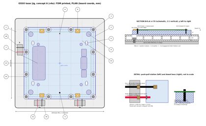
Oct 16, 2026 1:45 PM ET: Jig concept A (v4a), FDM first iteration
the designer: the first jig is an FDM print, made for iterating, not aluminum.
- Script: drawings/jig_v4a.py. Outputs: jig_v4a_p1.png (plan, section B-B, push-pull and dowel details), jig_v4a_p2.png (notes and FDM caveats), jig_v4a.pdf.
- Base: printed, 200x200x18, fits a bed of 210mm or larger. For a 180mm bed, split it into two 100x200 halves with a tongue-and-groove joint and 3 M4 bolts. 4mm skins top and bottom, with 3mm ribs on a 25mm grid. PLA+/PLA-CF, or PETG/ASA if it runs warm.
- Table screws: 12 M6 at the 25mm grid points on the ±75 ring. Ø13 counterbore with 6mm of plastic under the head, M6x12 with a DIN125 washer, about 4.4mm of engagement into the 4-5mm blind holes, low torque.
- Carrier: printed, 160x160x12, with the support face printed on the bed. It has Ø12 access holes over the M6 screws and 4 M4 lock screws in slots into heat-set inserts in the base.
- Dowels: ground h6 steel, press-fit with retaining compound into reamed 100%-infill bosses (printed Ø2.8/Ø1.8, then reamed). Ø3 at (70,4.0) sits 1.0mm above the board; Ø2 at (70,136.0) sits 0.5mm above.
- Fine adjust: push-pull with M3 screws in heat-set inserts. Station X is on the left; Y1 and Y2 are on the bottom side, 90mm apart, and their difference sets rotation. Range ±3mm; 1/8 turn = 0.06mm.
- Relief pockets, 2mm deep: window, slot, corner rings, fiducials, TH zones.
- 4 toe clamps on the y=0 and y=140 edges at x=30 and x=110 only.
- FDM caveats: flatness (consider a bonded aluminum or FR4 face), creep, dowel wear, UV laser hitting plastic (clip job images to the board, use metal or sacrificial-card-covered clamp tips and margins), heat (no reflow in the jig), and squeegee flex.
- Open: galvo center vs the table grid, and focal height. If the galvo center is off-grid, regenerate the base with the offset.
2026-10-16 1:48 PM ET — Jig registration plan
- Printer: Bambu P1S (256×256 bed), high-flow PETG, 0.6 nozzle. Jig base 200×200 prints in one piece. Next jig revision: switch notes from PLA to PETG and size walls/ribs for 0.6 nozzle.
- Software: LightBurn. Plan: galvo lens calibration, red-dot trace on fiducial A to set X/Y push-pull, fiducial B for rotation; Print and Cut as an alternative.
- Decision: jig base stays on-grid for now; offsets to the table grid get tuned once PCBs arrive and the designer reports how close it lands.
Oct 16, 2026 1:58 PM ET: Jig v4b 3D CAD (concept A)
- CadQuery 2.8 model, folder cad/jig_v4b/: jig_v4b.py (source), jig_v4b.step (assembly: base, carrier, ghost_board), jig_v4b_base.stl, jig_v4b_carrier.stl (support face on the bed), PRINT_NOTES.md, preview_*.png, verify.py.
- Target: Bambu P1S, HF PETG, 0.6 nozzle. Base is one piece, 200x200x18, modeled solid. Ribs come from the slicer: 5 walls, 40% gyroid, 100% modifiers at the dowel bosses, inserts and counterbore floors. Three push-pull posts (24x12, 12 mm tall) on the base top.
- Kept from v4a: 12 M6 (Ø6.6 thru, Ø13 cb, 6 mm floor) on the ±75 ring; carrier 160x160x12 with Ø12 access and 4 M4 4.5x10 slots over Ø5.6x10 insert holes; dowel bosses Ø2.8x10 at (70,4) and Ø1.8x9 at (70,136), to ream to Ø3/Ø2; 2 mm pockets (window, slot, TH zones, corner rings Ø11, fiducials Ø6); toe-clamp M3 inserts (Ø4.0x6.5) at x=30/110 on y=-3/143. M3 inserts are Ø4.0x6.5 and M4 inserts Ø5.6x10 (CNC Kitchen spec).
- Deviations: (1) the Ø12 access holes break out of the 160 carrier (the ring sits 5 mm from the edge), so they're modeled as open U-notches; (2) the X push-pull station moved from y=100 to y=70 to clear the M6 notch at y=95; (3) on Y1 the push/pull order is swapped (push x=30, pull x=20) so the pull insert misses the toe-clamp insert at (30,-3); (4) pockets have a 1 mm margin around the features, as in v4a; the mirror keepout lies inside the window pocket.
- Verified: STEP reimports as 3 valid solids; both STLs are watertight with consistent winding; probe points confirm the holes and pockets.
- Open: galvo center vs grid and focal height (offset still 0); toe-clamp hardware choice; dowel seat depths to set on assembly; flatness check after printing.
2026-10-16 2:45 PM ET — Version 4 frozen
- Snapshot: versions/v4_2026-10-16 + OSSO_v4_2026-10-16.tar.gz. Includes jig v4a drawings and jig v4b CAD (STEP/STL/print notes). Next snapshot: v5.


 OSSO