← v5 v7 →
v6: Top/bottom board v1a-v1g, unified companion window
Frozen Mon Oct 19, 2026, 12:55 PM ET · 235 files · folder: versions/v6_2026-10-19/ · archive: OSSO_v6_2026-10-19.tar.gz
What changed
New in this snapshot: 19 drawings, 8 STEP files, 1 documents/media.
Key decisions
Drawings new in v6
STEP files (15)
Documents & media
Journal entries in this version
2026-10-19 10:22 AM ET — CONCEPT: daisy-chaining multiple OSSO stacks
- the designer: with Pos and Neg terminals on both the left and right sides of the PCB, a chain of wires with circular ring terminals on both ends can link multiple OSSO stacks together.
- Implication: each stack can pass power in on one side and out on the other (stack-to-stack daisy chain), without a central distribution board.
- Open items: terminal style and stud size (e.g. M3, matching the corner hardware), wire gauge vs. the 5A rail rule, and whether chained current through a stack's terminals needs its own rating.
2026-10-19 10:25 AM ET — Pogo pin model (YZD0029-20135-01) at 12.0mm gap
- Built from LCSC datasheet drawing rev A.2: cad/pogo_YZD0029/ (compressed 12mm + free 13.5 STEPs, DIMENSIONS.md, preview PNG).
- FINDING: barrel is Ø1.50 (not 2.0); the Ø2.00 is the collar (0.50 thick), located at one END of the body, not center. Plungers Ø0.90, R0.45 tips; body 10.50; travel symmetric, 1.0/end to rated 11.5 working, 1.5/end max (10.5 min).
- At 12.0mm: 0.75mm/end compression (1.5 total vs 2.0 rated). Est. ~67gf vs 90gf rated (linear-spring estimate, no curve published). 0.75mm/end travel reserve remains.
- Interposer implications: ~Ø1.6 barrel hole, ~Ø2.1 counterbore for the collar; collar sits Z 0.75–1.25 above lower pad.
2026-10-19 10:25 AM ET — DECISION: 20A system max
- System (multi-stack chain) max is 20A: 12 AWG daisy-chain wire with matching ring terminals (12–10 AWG), 4 stacks × 5A.
- The first stack's terminals, ring pads and left-to-right pass-through path must be rated for the full 20A, not 5A (wide copper pour or off-board bus; TBD).
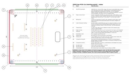
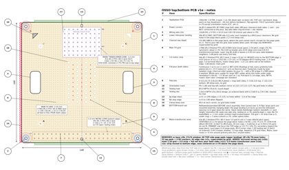
2026-10-19 11:00 AM ET — Top PCB v1a (starting point)
- New board type: the TOP PCB, the cap board of an OSSO stack. Nothing stacks above it, so its top side is the landing spot for large parts (transformers, tall caps, anything over the 10mm interposer-zone rule). Headroom is set by the 150mm enclosure: about 26mm over a 124mm 10-board stack, before hardware.
- Derived from base_v3b and the ordered blank v3b (fab/gen_v3b_gerbers.py, cad/blank_v3b/_parsed.json). Wireframe plan view, numbered callouts 1–15, notes table, overall dimensions only.
- REMOVED:
- The 27x74 R5 window at (10,33), the companion-board slot (base v3b callout 3).
- The UPPER interposer landing: 40 TOP-side (L1) Ø3.0 ENIG pogo pads. Reasoning: on the blank every pogo site has an isolated pad on each side at the same XY (journal Oct 15 12:35 PM, exploded v3b section A-A). The top-side pad takes the interposer above, and the bottom-side pad takes the interposer below. The block is symmetric about x=70, so the left-right flip alternation doesn't change which side is which, and no pads move.
- Both TH zones (48 Ø1.0 PTH, 2x 4x6). TH grids come back in a later step.
- Overlays that only made sense with a window or a board above: companion outlines, the wire-route keep-out, the printed interposer (ring, columns, spine) above the board, and the skyline cutouts.
- KEPT:
- The 140x140 R4 outline and the 12x26 R4 wiring slot at (118,57).
- 4 plated M3 Ø3.2 power corners with Ø7 rings on both sides. The top side takes the ring terminal for the bus feed.
- 40 BOTTOM-side Ø3.0 pogo pads (the lower interposer landing).
- 71 vias: 27 channel and 44 edge.
- Fiducials A/B (Ø0.4 plated) and C, and the pin-1 mark.
- The Ø3.0 NPTH tooling hole at (70,4) and the slot at (70,136).
- Jig edge stops, the no-stop edge, and the clamp keep-outs.
- 32 companion lap pads and 4 M2 Ø2.2 NPTH anchors. These were kept because they weren't on the removal list, but without a window they have nothing to bridge. the designer to decide whether to remove or reuse them.
- Notes: vias are shown as fabbed (Ø0.3 drill / Ø0.6 pad), which fixes the Ø0.6/Ø1.0 text left over from v3b. The slot is drawn at the 2.0x3.0 design intent; the blank v3b drill file routes 2.0x4.0. For the wiring slot to land over the window of the board below, the top board has to be flipped left-to-right relative to that board, which continues the alternation.
- Script: drawings/top_v1a.py. Outputs: drawings/osso_top_v1a.png and osso_top_v1a.pdf.
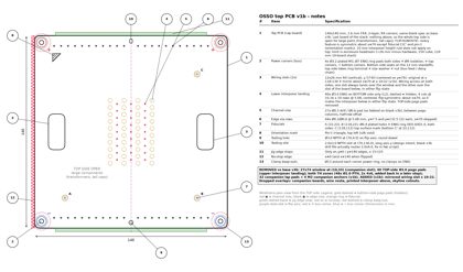
2026-10-19 11:05 AM ET — Top PCB v1b (symmetric wiring access)
- the designer's review of top_v1a resulted in two changes:
- REMOVED the 32 companion lap pads and the 4 M2 Ø2.2 companion anchors.
- ADDED a mirror of the 12x26 R4 wiring slot about the flip axis x=70: x 10–22, y 57–83. The board now has wiring access on both sides and is FLIP-AGNOSTIC. Whatever the flip state of the board below, one top-board slot lands over its window and the other over its wiring slot. The v1a note about flipping L-R relative to the board below is gone.
- Clearance check on the new slot (edge to edge, R4 ignored, so conservative):
- Fiducial A Ø5 keep-out: 32.5 mm.
- Bottom fiducial C' at (22,112), Ø5 keep-out: 26.5 mm.
- Nearest bottom pogo pad: 31.3 mm.
- Nearest via pad: 37.5 mm.
- Corner clamp keep-outs Ø13: 45.7 mm.
- Pin-1: 38 mm.
- Board edge x=0 (no-stop edge): 10 mm, the same web as the original slot to x=140.
- Inner edge of the interposer-below ring (x=6.5): 3.5 mm.
- No conflicts.
- Only the orientation marks (fiducial C/C' and pin-1) remain asymmetric about x=70, on purpose. The no-stop edge rule (x=0) is kept as a jig rule even though the companions that motivated it are gone.
- The board is now: the outline; 2 wiring slots; 4 power corners; 40 bottom-side Ø3.0 pogo pads (lower landing); 71 vias (27 channel + 44 edge); fiducials A/B/C; pin-1; tooling hole and slot; and the jig zones. Callouts are renumbered 1–13.
- Script: drawings/top_v1b.py. Outputs: drawings/osso_top_v1b.png and osso_top_v1b.pdf. The v1a files are unchanged.
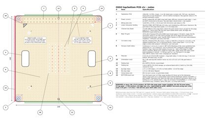
2026-10-19 11:10 AM ET — Top/bottom PCB v1c (TH grid + full pour)
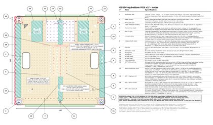
the designer approved v1c, built from v1b (the v1b files are kept). Script: drawings/top_v1c.py. Outputs: drawings/osso_top_v1c.png and osso_top_v1c.pdf. Title: "OSSO top/bottom PCB v1c". Callouts 1–16.
DECISION: main TH grid.
- 2.54 mm pitch, origin at (70,70), symmetric about x=70.
- 2072 holes, Ø1.0 finished PTH with a Ø1.8 ENIG land (mask open, per the no-bare-copper rule).
- Extents: x 3.96–136.04 (53 columns), y 3.96–125.88 (49 rows).
- Why Ø1.0/Ø1.8: it matches the v3b TH zones and takes 0.64 sq header pins (0.91 diagonal) and most 0.8–0.9 transformer and coil leads. With a laser isolation ring at Ø1.8–2.2 there is still a 0.34 mm pour web between neighbors.
- Parts on 5.08 pitch use every second hole.
DECISION: one 5.0 mm metric strip.
- 44 holes, Ø1.3 finished PTH with a Ø2.5 land, in 2 rows (y=130 and 135) of 22 at x=70±5k, which gives x 15–125.
- x=70 is left open for the tooling slot.
- It sits on the top edge so terminal-block wires exit outward.
- Ø1.3 suits 5.0 terminal blocks and mains relays (pins about 1.0–1.2).
- 5.08 blocks go on the main grid instead.
- The main grid stops at y=125.88, leaving a 1.97 mm land-to-land gap to the strip.
DECISION: full pour plus grid.
- Continuous 1 oz copper on L1 and L2. Every grid and strip hole is plated and tied into it, at about 15.5 holes/cm², so the holes also act as thermal vias.
- The pour is NET-LESS (floating) at fab. All 4 corners keep a Ø9 clearance on both sides, so + and − are never shorted to it. If a GND plane is wanted, bridge the pour to − with a 0R part across the isolation gap.
- Footprints come later: laser isolation rings and thermal-relief spokes.
- The whole pour can take large SMT parts. No separate SMT zones are marked.
- Cautions:
- Solder wicks into grid holes under SMT pads; tent or plug them where that matters.
- Plan on roughly 3–5 W per part on 1 oz copper.
- For mains, laser-clear the creepage distance the standard requires.
Clearances. The first exclusion reason found for each grid point:
| Reason |
Points excluded |
| Pogo block (pads +1.5 mm; bottom pads keep their Ø4.0 isolation) |
315 |
| Wiring slots (1.0 mm from the land) |
132 |
| Metric strip band |
182 |
| Clamp/corner Ø13 |
52 |
| Fiducial Ø5 (A, B, C, C') |
30 |
| Pin-1, top and bottom |
18 |
| Tooling hole |
4 |
| Tooling slot (cleared for the as-ordered 2.0x4.0) |
4 |
| Board edge (more than 3.5 mm in) |
216 |
DECISION: vias.
- The 44 edge vias are removed; the grid supersedes them.
- The 27 channel vias stay. They are inside the pogo block, where the grid can't go, and give the pogo pads their escape to L1. They are tied to the pour and get laser-isolated when used.
DESIGN NOTE (the designer): bottom-board use.
- This board can also go at the bottom of a stack, turned over (L-R flip) so the L2 pogo landing faces up to the interposer above. Large parts on L1 then hang below the stack.
- The geometry supports it:
- pads are on one side only;
- every functional feature is symmetric about x=70;
- the tooling hole and slot are on x=70;
-
- stays on top under the L-R flip;
- fiducials A and B are plated on both sides, and C' is on the bottom.
- Caveats:
- The stack needs feet or longer bottom standoffs, at least as tall as those parts.
- In this orientation, 392 grid holes and 22 strip holes (strip row y=135) sit under the printed ring, crossbars, or spine. Their TH leads and fillets on L2 must be trimmed flush, at most about 1 mm, or not used there.
2026-10-19 11:33 AM ET — DESIGN NOTE: top/bottom board used as bottom board
- the designer: the bottom board is reflowed before stack assembly, so its large components are mounted on the inverted side and hang downward. The pogo landing then faces up into the interposer above, and the interposer spacing (12.0mm gap, 13.6mm pitch) stays the same as for every other board.
- Same board design serves as top board (large parts up) or bottom board (flipped, large parts down). Requires stack feet / base clearance at least the height of the hanging parts.
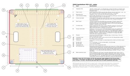
2026-10-19 11:35 AM ET — Top/bottom PCB v1d (mains transformer zone)
the designer: keep the 5.0 metric strip as it is, and add a 5.0 mm 2D grid area for a mains PCB transformer. The v1c files are kept. Script: drawings/top_v1d.py. Outputs: drawings/osso_top_v1d.png and osso_top_v1d.pdf. New callout 17.
DECISION: mains transformer zone.
- 63 holes, 9 columns x 7 rows on a 5.0 grid, Ø1.3 finished PTH with a Ø2.5 land (same as the strip). All tied into the net-less pour.
- Hole centers: x 27–67, y 8–38. The pitch span is 40x30 and the land envelope is 42.5x32.5. The zone sits lower-left of the pogo block.
- It fits EI30–EI38 class parts. Example: Block VB EI30, body 32.8x27.8x24.4, pins Ø0.8, rows 20 mm apart (the drawing shows its body outline for reference). 0.250" US parts such as the Triad FS12-090 don't fit, which was accepted.
- The 5.0 strip did NOT move.
Placement search. I swept 0.5 mm steps over the board with these clearances:
- 6 mm land-to-pad to the pogo block (creepage);
- the clamp Ø13 keep-outs plus 6 mm to the corner rings;
- 2 mm to the slots and tooling;
- the fiducial Ø5 keep-outs plus 1 mm;
- pin-1;
- the strip band.
Results:
- No 9x9 field fits.
- The only 8x8 fields swallow a fiducial. The best is at (7,17), which covers fiducial A and runs 0.75 mm into the bottom-use interposer ring shadow.
- No position on the x=70 axis works. Below the block the tooling hole, the spine shadow and the pogo creepage block it; above the block there is only about 31 mm before the strip band.
- 9x7 fits cleanly at x0=27 or at its mirror, x0=73. I chose x0=27.
Two consequences:
- The zone is off-axis, so it is the one feature that isn't flip-symmetric. Registration and the stack interface are still flip-agnostic.
- With 7 rows the zone is 30 mm deep, not 40. That is still enough for a 20 mm pin-row spacing in either orientation.
Clearances and hole counts.
- 279 holes are removed from the 2.54 grid (zone plus a 2.0 mm web); the minimum web left is 2.39 mm. The main grid drops from 2072 to 1793 holes.
- Land-to-pad distance to the pogo block is 6.39 mm. Distance to the nearest (−) corner ring is 17.45 mm.
- In bottom-board use, 7 zone holes (the x=67 column) sit under the edge of the spine shadow.
- Mains note: laser-cut an isolation moat of at least 6 mm around the primary pins, including any unused plated holes inside it, which would otherwise be floating islands. Face the primary row away from the pogo block, toward x=27 or y=8.
DESIGN NOTE (the designer): bottom-board use. The board is reflowed and assembled before stack assembly, then turned over. The large parts are mounted inverted and hang down, so the pogo landing faces up and the interposer spacing stays at 12.0 mm. This is now in callout 16.
2026-10-19 12:00 PM ET — Top/bottom PCB v1e (strip to bottom edge, centered transformer zone)
the designer chose option 2. The v1d files are kept. Script: drawings/top_v1e.py. Outputs: drawings/osso_top_v1e.png and osso_top_v1e.pdf.
DECISION: 5.0 metric strip moved to the BOTTOM edge.
- It is the exact mirror of v1c about y=70. 2 rows at y=5 and y=10, 22 per row at x=70±5k (x 15–125), so 44 holes, the same as before. Ø1.3 finished PTH with a Ø2.5 land, 5.0 pitch.
- x=70 is skipped, now for the Ø3.0 tooling hole: 2.35 mm land gap.
- The 2.54 grid now starts at y=14.12, with a 1.97 mm web to the strip (mirror of v1c).
DECISION: transformer zone CENTERED on x=70, above the pogo block.
- Full 9 cols x 7 rows: 63 holes, Ø1.3 finished PTH with a Ø2.5 land. Hole centers x 50–90, y 101.75–131.75. The pitch span is 40x30 and the land envelope is 42.5x32.5.
- Fit: EI30 rows 20 mm apart are 4 pitches in y, with pins along x. The PRIMARY row faces the TOP edge (y 131.75 or 126.75); the secondary row faces the pogo block.
- The y position has only 0.14 mm of freedom. It is bounded by 6 mm to the pogo pads and 1.0 mm to the as-ordered slot.
Land-edge clearances:
| To |
Gap |
| Pogo pads |
6.14 mm (≥6 OK) |
| Corner rings |
40.4 mm |
| Tooling slot, as ordered 2.0x4.0 |
1.00 mm (1.5 mm to the 2.0x3.0 design) |
| Top-crossbar shadow (bottom use) |
0.04 mm, tangent, not under |
| Top edge |
7.0 mm |
| Fiducial keep-outs |
24.25 mm |
| Pin-1 (bottom mirror) |
29.75 mm |
| Wiring slots |
32.45 mm |
| Clamp keep-outs, jig edge stops |
clear |
Symmetry. The board is now FULLY symmetric about x=70 except the orientation marks (C/C' and pin-1). The script asserts this for the grid, strip and zone.
2.54 grid.
- Restored where the old v1d zone and the old top strip band were.
- Re-cleared around the new zone (2.0 mm web, minimum 2.14 mm): 274 holes removed.
- The bottom band (y<13) is cleared for the strip.
- Main grid: 1798 holes (v1d: 1793; v1c: 2072).
Bottom-board shadow (holes under the printed interposer when the board is turned over):
- 316 grid holes.
- 22 strip holes: the whole y=5 row is under the ring band (0.5–6.5). The y=10 row is clear, and none are under the spine.
- 7 zone holes: the x=70 column is under the spine, which runs x 67.7–72.3 from y 100.46 to 133.5.
- Leads at those holes must be trimmed flush (at most about 1 mm) or left unused.
Mains. Laser-cut an isolation moat of at least 6 mm around the primary pins. It must take in any unused plated holes, including the restored 2.54 rows above the zone (y 133.5–136) and the zone's own spare holes.
2026-10-19 12:12 PM ET — Top PCB v1f (NO-TH SMT zones)
the designer asked for "a bit of all of these zones". The v1e files are kept. Script: drawings/top_v1f.py. Outputs: drawings/osso_top_v1f.png and osso_top_v1f.pdf. New callouts 18–20.
What an SMT zone is. Solid pour on both sides with no grid holes. Large SMT parts go there without solder wicking into holes. In bottom-board use, it is also where nothing pokes up into the printed interposer. Vias, pogo pads, corners, tooling, fiducials and pin-1 are unchanged. Every zone is mirrored about x=70, so the board is still symmetric except the orientation marks; the script asserts this.
| Zone |
Rect (x, y) |
Size |
Removed |
| SMT-1L / 1R ring band |
x 0–7.8 / 132.2–140, y 11.5–128.5 |
7.8 x 117 each |
180 grid (2 columns x 45 per side) |
| SMT-2B spine, bottom |
x 66.6–73.4, y 6.5–44.14 |
6.8 x 37.64 |
38 grid in total for 2B + 2T, net vs v1e |
| SMT-2T spine, top |
x 66.6–73.4, y 95.86–133.5 |
6.8 x 37.64 |
plus 7 zone holes (x=70 column) |
| SMT-3L / 3R flank pads |
x 25.0–42.0 / 98.0–115.0, y 100.5–133.0 |
17.0 x 32.5 each |
220 grid (110 per side) |
- SMT-1 covers the ring band (0–6.5) plus 1.3 mm and runs between the Ø13 clamp keep-outs. Uses: edge connectors (Kyocera 9296 poke-home) and 12AWG daisy-chain pads next to the +/− corners. It is 2.0 mm from the Ø9 corner isolation. The x=9.04 column stays, with a 0.34 mm land web.
- SMT-2 is a 6.8 mm corridor over the 4.6 mm spine shadow (67.7–72.3). 2B reaches up through the bottom crossbar shadow. 2T runs from the top crossbar to the ring.
- SMT-3 fits one D2PAK (about 10.8x15.9 land) above one 10 mm-class shielded inductor. Its grid web is 1.0 mm.
Grid removal rule: a hole is removed when its land comes within 0.3 mm of an SMT-1 or SMT-2 rect, or within 1.0 mm of an SMT-3 rect.
DECISION: transformer zone is now 8 columns x 7 rows = 56 holes. Columns are x 50–65 and 75–90 (x=70 dropped); rows are y 101.75–131.75 as before. A part that needs a pin on x=70 has to shift 5 mm off-axis. Distance to the as-ordered tooling slot is now 3.71 mm (was 1.00).
DECISION: strip y=5 row DROPPED rather than shifting the strip 5 mm inward.
- Shifting would push the strip into y 10/15, cost about 2 rows of the 2.54 grid, and change the grid/strip web.
- Dropping it changes nothing else. The strip is now 1 row at y=10, 22 holes, x 15–125 with x=70 skipped.
- The y<13 band under it stays plain pour.
Totals.
|
v1f |
v1e |
| Main grid |
1360 |
1798 (−438) |
| Strip |
22 |
44 |
| Transformer zone |
56 |
63 |
Bottom-board shadow (holes still under the printed interposer):
- 82 grid holes: 52 in the unconverted top ring-band rows (y 133.5/136.04) and 30 under the crossbars (24 bottom, 6 top).
- 0 strip holes and 0 zone holes.
- v1e had 316 + 22 + 7.
Clearances.
| Item |
Gap |
| SMT-3 to zone lands |
6.75 mm, so 0.75 mm OUTSIDE the ≥6 mm moat (moat x 42.75–97.25, y 94.5 to the top edge) |
| SMT-3 to fiducial C/C' Ø5 keep-out |
0.5 mm (tightest) |
| SMT-3 to pin-1 |
6.0 mm |
| SMT-3 to top edge |
7.0 mm |
| SMT-3 to tooling slot |
27 mm |
| SMT-2T to tooling slot (as-ordered 2.0x4.0) |
0.5 mm |
| SMT-2B to tooling hole |
1.0 mm |
| SMT-2 to zone and strip lands |
0.35 mm |
Mains moat (drawn red dotted).
- Only 7 mm separates the zone lands from the top edge, so the moat runs out to the top edge. It takes in the tooling slot (NPTH, no copper) and all of SMT-2T. SMT-2T is inside the mains area: use it only for primary-side parts, or not at all.
- 68 unused 2.54 holes sit inside the moat, 22 of them above the zone. They must be cut out with it.
- The moat stops 0.14 mm short of the pogo pads, the same as in v1e.
2026-10-19 12:36 PM ET — DECISION (the designer): unified companion board size
- The 5.0 mm mains transformer zone becomes a COMPANION BOARD.
- Every companion in the system uses ONE size and window: the base 27x74 R5 window at (10,33), with 32 lap pads (2.0x1.0 @ 2.54) and 4 M2 Ø2.2 NPTH anchors, as in base v3b / gen_v3b_gerbers.
- A companion can carry 5.0, 3.96, 3.5 or a custom pitch. A mains companion holds transformer + fuse/MOV/X-cap/bridge with its own isolation, so the top board no longer needs a mains moat.
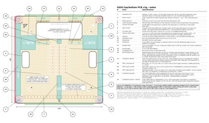
2026-10-19 12:44 PM ET — Top PCB v1g (unified companion window)
The v1f files are kept. Script: drawings/top_v1g.py. Outputs: drawings/osso_top_v1g.png and osso_top_v1g.pdf. Geometry for CAD: drawings/top_v1g_geom.json. Callouts 21 (lap pads) and 22 (anchors + companions) are new.
DECISION: companion window placement. The base window, lap pads and anchors are ROTATED 90° CW about the board centre: (bx,by) → (by, 140−bx). Nothing else moves. That gives:
- Window: 74x27 R5 cutout at x 33–107, y 103–130, centred on x=70.
- Lap pads: 32x 1.0x2.0. Inner row at y 101.4, outer row at y 131.6. x 34.50–52.28 and 86.50–104.28 at 2.54, 8 per row per companion.
- Anchors: Ø2.2 NPTH at x 38/50/90/102, y 97.2.
- Companion outlines: 22x45.5 at x 33–55 and 85–107, y 94.5–140. The outer edge sits at the board edge, as on base x=0.
- Orientation: the outer (10 mm) side faces the top edge and the anchors face the pogo block, the same as on base.
Clearances (edge to edge, mm):
| From |
To |
Gap |
| Window |
pogo pads |
8.64 |
| Anchors |
pogo pads |
3.84 (3.34 to the Ø4 isolation) |
| Inner laps (L1) |
pogo pads (L2) |
6.04 |
| Window |
tooling slot, as-ordered 2.0x4.0 |
4.0 |
| Window |
tooling slot, 2.0x3.0 design |
4.5 |
| Companions |
tooling slot |
14 |
| Window |
top edge |
10 |
| Outer laps |
top edge |
7.4 |
| Window |
fiducial C/C' keep-outs |
8.5 |
| Companions |
fiducial C/C' keep-outs |
8.5 |
| Window |
Ø13 clamp keep-outs |
21.9 |
| Companions |
Ø13 clamp keep-outs |
21.5 |
| Companions |
pin-1 |
14 |
| Window |
wiring slots |
22.8 |
Bottom-board use. Laps and companions are on L1 only, so only the window and anchors reach L2.
- Window to top crossbar: 2.54. Window to ring band: 3.5. Window to columns: 7.14.
- Anchors to crossbar: 1.36; to columns: 1.70. An M2 head or nut is roughly Ø3.8, so allow about 0.5 mm.
- The interposer spine (x 67.7–72.3) bridges the window over 27 mm in the centre gap (x 55–85), where there is no companion. Tall parts there can't rise past L2 under the spine.
- Companion outlines run to y=140 under the jig edge stop. Companions are mounted after the jig steps.
Lap-pad symmetry. The pads are an exact translation copy of the base, so any companion fits both boards. Both companions are the same board, translated, not mirrored. As a result, the right pad set is 1.22 mm off the mirror of the left. The anchors are symmetric. A system-wide fix would centre 8 pads in 22 mm, starting 2.11 from the end. That changes the base and is not done.
Zone changes.
- The transformer zone (56 holes) and the 6 mm moat are REMOVED.
- SMT-3 is moved and reshaped: x 9.0–32.0 / 108.0–131.0, y 86.0–108.5, 23.0x22.5 each. It takes a D2PAK and a 10 mm inductor side by side. Gaps: 1.0 to the companion outline, 1.0 to the fiducial keep-out, 3.0 to the wiring slot, 1.2 to SMT-1.
- SMT-2T is shortened to y 95.86–102.0 (6.8x6.14).
- SMT-1 and SMT-2B are unchanged.
Holes.
- Main grid: 1194 (v1f: 1360). 78 were restored where the zone, moat, old SMT-3 and old SMT-2T were. 244 were removed: 80 for the companion (24 window, 4 laps, 14 anchors, 38 under the companion outlines) and 164 for the new SMT-3.
- No grid is left under the companion outlines, because exposed ENIG lands would short the companion's bottom copper.
- The strip is unchanged at 22. Holes under the interposer in bottom-board use: 86 grid holes.
Second window position.
- Mirror about y=70 (window y 10–37, companions y 0–45.5): geometrically OK. Gaps are 2.54 to the bottom crossbar, about 3.8 to the pogo pads, and 4.5 to the tooling hole. It would cost 14 of the 22 strip holes (x 35–105) and cut SMT-2B. Not drawn; it is an option if two companions are wanted.
- Upright at the base position (10,33): it collides with the mirrored wiring slot at x 10–22, so it is not feasible without dropping that slot.
2026-10-19 12:55 PM ET — STEP models for Fusion (middle/base + top v1g)
Folder: cad/top_middle_v1g/. Script: make_top_middle_v1g.py (needs drawings/top_v1g_geom.json). Verify: verify.py, which reimports every STEP. Colors: black mask, gold ENIG, green companion, grey/blue/beige representative parts.
- Middle: OSSO_middle_base_v3b_board.step (rebuilt from the v3b fab files) and OSSO_middle_base_v3b_with_companion.step, with one unified 45.5x22 companion at (0,33) in the window (16 lap pads, 2 anchors) and representative parts.
- Top: OSSO_top_v1g_board.step (full 1194-hole grid, 22 strip holes, pads, window, slots, corners) and OSSO_top_v1g_with_mains_companion.step.
- Companion-only files: OSSO_companion_unified_45p5x22_board.step and OSSO_companion_mains_double_74x39_board.step.
- The mains companion is a DOUBLE-WIDTH board, 74x39 at x 33-107, y 94.5-133.5, soldered to both lap-pad sets. A 38x32 EI38 body does not fit a single 22 mm companion. This is a modeling choice and needs the designer's confirmation. Transformer body, pins, fuse, X2, MOV and bridge are representative only.
2026-10-19 12:55 PM ET — Version 6 frozen
versions/v6_2026-10-19 plus OSSO_v6_2026-10-19.tar.gz. Adds top/bottom PCB v1a–v1g (strip, 5mm zone, NO-TH SMT zones), the decision to use the unified 27x74 companion window rotated across the top (transformer becomes a companion; double-width 74x39 mains companion modeled, needs the designer's OK), and STEP models in cad/top_middle_v1g/ (sent to the designer's Downloads). Open: mains companion size, lap-pad 1.22mm asymmetry, spine over window in bottom-board use, base drawings still need 12mm gap update.